Download
1 / 22

E N D
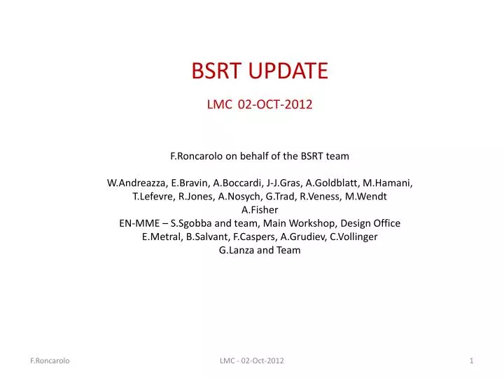
BSRT UPDATELMC02-OCT-2012F.Roncarolo on behalf of the BSRT teamW.Andreazza, E.Bravin, A.Boccardi, J-J.Gras, A.Goldblatt, M.Hamani, T.Lefevre, R.Jones, A.Nosych, G.Trad, R.Veness, M.WendtA.FisherEN-MME –S.Sgobba and team, Main Workshop, Design OfficeE.Metral, B.Salvant, F.Caspers, A.Grudiev, C.VollingerG.Lanza and Team LMC - 02-Oct-2012
Recap - TS#3 Actions • BSRT mirrors before TS#3: silicon bulk + dielectric coating • After B2 mirror removal end of August (coating blistered) and suspect of same damage on B1 mirror, three options for TS#3: • Spare mirror: Silicon bulk + dielectric coating • Option dropped, good choice after B1 mirror removal (coating blistered) • Spare mirror after coating removal and polishing pure silicon mirror • Installed on B2 • New mirror: glass bulk + metallic (Al) coating • Installed on B1 • On both B1 and B2: • Failsafe mirror supports • Inconel mirror clamps • Ferrites with higher Curie temperature – increase ferrite volume See LMC 14 Sep 2012 LMC - 02-Oct-2012
B1 Mirror removal Evidence of blistering Decided not to install an identical mirror Mirror out of place LMC - 02-Oct-2012
B1 refurbishment during TS#3 • Mirror: glass bulk+ metallic (Al) coating • Imaging optics changed from focusing mirrors to focusing lenses • Change already scheduled in advance, independently from August’s systems failure • Alignment with calibration laser as done with old optics OLD: 2 focusing + 8 folding mirrors NEW: 2 focusing lenses + 2 folding mirrors A.Goldblatt, A.Fisher LMC - 02-Oct-2012
B1 performance @ re-start • Steering to find light spot very similar to what expected after laser alignment • Amount of light ~ as expected, ~ = dielectric coating (maybe even better, to be characterized) • Preliminary calibration w.r.t. WS (next slides) LMC - 02-Oct-2012
BSRT vs WS B1 HOR 4 TeV BSRT Correction in quadrature: 0.21 mm (was 0.38 mm) G.Trad LMC - 02-Oct-2012
BSRT vs WS B1 VER 4TeV BSRT Correction in quadrature: 0.23 mm (was 0.35 mm) G.Trad LMC - 02-Oct-2012
B2 refurbishment during TS#3 • Mirror: polished Silicon bulk, no coating • Imaging optics (focusing mirrors) unchanged • Re-alignment with calibration laser • Imaging of calibration target Illuminated target Target calibration line BSRT Camera Optical table top view Extraction mirror (vacuum) + steering mirror (air, first mirror on the table) Imaging calibration target as before TS#3 no evidence of image distortion on all mirrors apart from Extraction + Steering mirrors LMC - 02-Oct-2012
B2 observations @ re-start • Steering to find light spot very similar to what expected after laser alignment • Amount of light ~ as expected after removing coating (~ factor 2 less w.r.t. coated mirror) • Bad surprise looking at image quality 450 GeV 4 TeV LMC - 02-Oct-2012
B2 Scan mirror IN OUT 4 TeV 4 Proton beam BSRT mirror Proton beam BSRT mirror Sync. Light Sync. Light MIRROR IN MIRROR OUT 1 2 3 1 0 Conclusion: Moving mirror out loose image ‘core’, ‘fringes’ remain N.B.: tried same exercise on B1 no evidence of distorted images… LMC - 02-Oct-2012
B2 Selecting different wavelengths 4 TeV All wavelengths Blue Red Green Red • Larger radiation wavelength larger ‘fringes’ distance compatible with diffraction LMC - 02-Oct-2012
4 TeV B2 Horizontal Closed Orbit Bumps Proton beam BSRT mirror Bump - Bump + Sync. Light 70 mm +4mm Bump NO bump 0 +2mm Bump • In all these cases: camera gain to have maximum ‘fringes’ visibility • Bump + weight of ‘fringes’ w.r.t. ‘core’ decreases -4mm Bump LMC - 02-Oct-2012
B2 Horizontal Closed Orbit Bumps 4 TeV Setting camera gain as in operational mode (no saturation) NO bump, low gain Anyway: emittances from Gaussian fits give unphysical large emittance +4mm bump, low gain • N.B. : • absolute position on screen depends on steering (not the same for these two acq.) • Verified that steering ( different path inside telescope) doesn’t change ‘fringes’ shape and weight LMC - 02-Oct-2012
Temperatures Probes Flange 1 Flange 2 View Port 1 View Port 2 Bellow See Measurements next slide LMC - 02-Oct-2012
Temperatures Before TS#3 (‘bellow’ probe B1 not at same location as B2) • After TS#3 • ‘bellow’ probe B1 displaced to be = B2 • Added 2 probes on flange 1380 b BEAM 1 1380 b Bellow View Port Mirror OUT Flange 1380 b LAMP ON Mirror IN 1380 b 1380 b Bellow Flange BEAM 2 Mirror Falling View Port 1380 b • B1 heating ~= B2 heating • Bellow heats more and faster than flange (== radiation more than conduction?) LMC - 02-Oct-2012
Vacuum 5.L4 BSRT B2 , baked out during TS#3 …. LMC - 02-Oct-2012
Summary of Observations after TS#3 • B1 ok, need to verify if survives to thermal cycles • New optics base on lenses seems better for overall resolution and accuracy, to be confirmed • B2 image ‘distortion’ to be understood • edge effect? • Bad surface polishing? • Silicon not suitable for imaging? • Optics after extraction mirror misalignment? • No clear evidence of less heatingw.r.t before TS#3 for both B1 and B2 • No clear evidence of B1 (metallic coating) heating more than B2 • Both B1 and B2 AGM operational despite bad B2 imaging. Calibration checks on-going, need to verify calibration stability over time LMC - 02-Oct-2012
Plans - Proposals • ASAP: • access 3 hours re-check alignment B2 with calibration laser exclude (or not) any source of uncertainty other than the extraction mirror itself • Test imaging system based on pure silicon mirror in the lab (on-going) • Before MD3 (if possible) • B2 Bumps (450 GeV and/or 4 TeV) + move mirror out with bump >= 4mm IN assess it’s only an edge effect or not • MD3 • B1: Precise Calibration w.r.t WS • B2: points above if not possible before • If enough time: B1&B2, characterize heating with high intensity beams at 450 GeV • Wait between injections to cope with thermal inertia and establish whether there is a threshold effect or not • TS#4 (xstmas) • depending on possible new observations/understanding, e.g. will B1 mirror survive thermal cycles? • Open B2 and replace mirror with copy of B1 (glass + metallic coating) • If new B1 optics full validated • Replace also B2 optics with focusing lenses based system • LS1: depending on end of the run experience + improved RF and thermo-mechanical simulations • Redesign mechanics to minimize RF coupling • Active cooling • … LMC - 02-Oct-2012
SPARE LMC - 02-Oct-2012