Download
1 / 21
210 likes | 289 Views
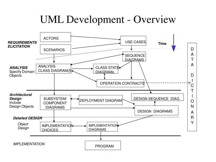
SCENARIOS. ACTORS. USE CASES. UML Development - Overview. REQUIREMENTS ELICITATION. Time. D. A. SEQUENCE DIAGRAMS. T. A. ANALYSIS CLASS DIAGRAM(S). CLASS STATE DIAGRAMs. ANALYSIS Specify Domain Objects. D. I. OPERATION CONTRACTS. C. T. Architectural Design Include

E N D
SCENARIOS ACTORS USE CASES UML Development - Overview REQUIREMENTS ELICITATION Time D A SEQUENCE DIAGRAMS T A ANALYSIS CLASS DIAGRAM(S) CLASS STATEDIAGRAMs ANALYSIS Specify Domain Objects D I OPERATION CONTRACTS C T Architectural Design Include Design Objects I SUBSYSTEM/ COMPONENT DIAGRAMS DESIGN SEQUENCE DIAG. DEPLOYMENT DIAGRAM O N DESIGN DIAGRAMS A R Detailed DESIGN Y Object Design IMPLEMENTATION CHOICES IMPLEMENTATION DIAGRAMS IMPLEMENTATION PROGRAM
Information Available and Artifacts Developed at Architectural Design • Use cases, Use case Diagram • Analysis and Arc. Design class diagrams • Analysis and Arc. Design Sequence/Collaboration diagrams • Statecharts for multi-modal classes • Subsystems + their public interface (API) • Subsystem dependencies • Mapping subsystems’ instances to Hardware (Deployment) • Data management, Security control
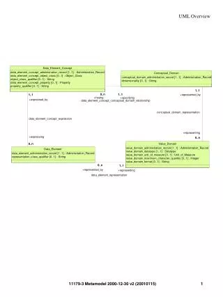
RouteAssistant PlanningService Trip Location Direction Destination Crossing Segment MyTrip Analysis Class Diagram
PlanningSubsystem RoutingSubsystem RouteAssistant PlanningService Trip Location Direction Destination Crossing Segment MyTrip Subsystems
Subsystem Interface • The set of public operations forms the subsystem interface or Application Programming Interface (API) • Includes operations but also their parameters, types, and return values • Operation contracts are also defined (pre- and post-conditions) and accounted for by client subsystems – they can be considered part of the API
Components vs Subsystems • A Component are used to implement a package of classes defined in a subsystem • A component defines a module in the architectural design • Component types defined by component stereotypes include a Main program component, and Tasks • Task components represent packages or subsystems with independent threads of control
:OnBoardComputer :WebServer :PlanningSubsystem :RoutingSubsystem MyTrip Deployment Diagram Components must be associated with a processor node in the deployment diagram
PlanningSubsystem RoutingSubsystem RouteAssistant PlanningService Trip Location Destination TripProxy Direction Crossing SegmentProxy Segment CommunicationSubsystem Message Connection New Classes and Subsystems
RoutingSubsystem PlanningSubsystem CommunicationSubsystem TripFileStoreSubsystem MapDBStoreSubsystem MyTrip Data Storage
Static versus Dynamic Architecture Information • Subsystem Interfaces and dependencies provide static information • Interaction models provide dynamic information • Concurrency information can be specified on objection collaboration diagrams, sequence diagrams, and component diagrams
Concurrency Adornment • The concurrency of a class is a statement about its semantics in the presence of multiple threads of control. You can set the concurrency of a class to type Active • The class will has its own thread of control. The method can be executing concurrently with other methods. • You can display the concurrency for the class in the class diagram by selecting Show Concurrency from the class shortcut menu.
Concurrency in Sequence Diagrams Synchronous method invocation for sequential execution
Concurrency in Sequence Diagrams • Asynchronous method calls should be explicitly identified with the UML standard notation of a solid line with a half arrowhead. • Asynchronous messages do not yield the current thread of control. • Therefore, from the initiating object's viewpoint, there is no implied return message or waiting
IETM Object Model Interfaces Data Services Business Services User Services Proposed Component-based IETM Display System Architecture IETM Object MIL-PRF-87269A Alternative Model COTS Components Web Technologies
Web page + Scripts Applet Jbeans ActiveX Forms Style info if not processed on server IETM Navigation Handler (Requires IE5) GUI Manager User Interface Engine HTTP, IIOP, DCOM Receive-Request Render-Info Web Server Browser Receive-Response Send-Request Send-Response Plugins or Helper Applications Might require a Media Viewer Media Server User Interface
IETM Object Model IETM Object Model Interfaces XML/HTML Transformer (XSL Processor) IETM EDS IETM Receive-Request Interpreter Get-Result- Get-IETM- Receive- Response Objects Objects Web IETM Display Server Engine Search Start Update Get Add Remove Send-Response CGI Servlet EJB CORBA Beans VB, Java, ECMA Scripts ASP, JSP Session Manager Optional: Use it to allow rendering on all browsers not just IE5 Session Session Cache State
O/DBMS + ORB CORBA Server CORBA/IIOP Database on O/DBMS Server XML on O/DBMS Server Database to DOM Relational to Object Mapping Vendor Driver + ODBC or JDBC Driver IETM Database Object Interface Data Content Loader Get-Info Get-Result- Objects XML/HTML SQL OQL SQLJ IETM Transformer (XSL Processor) Interpreter Style Info Data AccessDatabase-driven System
IETM Object Model Architectural Forms in UML Architectural-Forms id : ID 1..* 1..* cdm : NAME ref : IDREF <<Stereotype>> <<Stereotype>> IF-NODE LOOP-NODE Condition : expression 0..* 0..* InformationContent-Forms IndexDeclare [0..1] : assertion ThenSeq : NODE-SEQ ExitCond : expression ElseSeq [0..1] : NODE-SEQ IndexAlter [0..1] : assertion RepeatSeq : NODE-SEQ selectFlow() getThenSeq() Start() Eval_Condition() Update_Index() Terminate() <<Stereotype>> NODE 1 1 name : CDATA type : CDATA itemid : CDATA <<Stereotype>> preconditions [0..*] : precond 1 1 NODE-ALTS postconditions [0..*] : postcond <<Stereotype>> Contents : InformationContent-Forms Nodes : NODE NODE-SEQ 1..* 1..* 1 1 primitives [0..*] : %primitive links [0..*] : %link SeqElements : Architectural-Forms Eval_Alts() 1 1 Display() getNextElement() Set_Post_Conditions() stepBack() 1 1 Eval_Pre_Conditions() hasMoreElements() Reset() hasContents()
IETM Object Model The IETM Object Model Interfaces