Download
1 / 50
510 likes | 539 Views
COMET Approach for UML Overview. Chapter 6. Designing Concurrent, Distributed, and Real-Time Applications with UML Hassan Gomaa (2001). COMET. C oncurrent O bject M odeling and architectural design m ET hod

E N D
COMET Approach for UML Overview Chapter 6 Designing Concurrent, Distributed, and Real-Time Applications with UML Hassan Gomaa (2001)
COMET • Concurrent Object Modeling and architectural design mEThod • Textbook: Designing Concurrent, Distributed, and Real-Time Applications with UML (Hassan Gomaa)
Modeling Language vs Method • Select Best Approach to Blueprints
UML design example (e.g. IEEE 1471 architectural description standard)
SysML vs UML • SysML has advantages over UML for specifying systems and systems-of-systems: • Expresses systems engineering semantics with more accuracy, adding two new diagram types for requirements management and performance analysis (Requirement diagrams and Parametric diagrams). • Easier to learn than UML with less diagram types (9 vs. 13) and total constructs. • Facilitates automated verification and validation (V&V) and gap analysis. • Model management constructs support the specification of models, views, and viewpoints and are architecturally aligned with IEEE-Std-1471-2000 (IEEE Recommended Practice for Architectural Description of Software-Intensive Systems). • http://www.sysmlforum.com/FAQ.htm
SysML Diagram Taxonomy SysML Diagram Structure Behavior Parametric Requirement Diagram Diagram Diagram Diagram Activity Timing Assembly Class Use Case Diagram Diagram Diagram Diagram Diagram Sequence State Machine Diagram Diagram Diagram category As-is from UML 2 Interaction Overview Diagram Modified from UML 2 New diagram type As of v0.90
What is COMET? • COMET is a design method for UML supporting OO systems • Concurrent • Distributed • Real-Time • Concurrent Object Modeling and architectural design mEThod • Compatible with USDP (Unified Software Development Process)
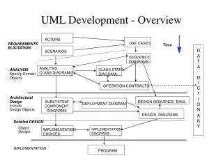
COMET Software Lifecycle (6.1) • A highly iterative process • Focuses on the use case concept • Functional requirements are recorded in terms of actors and their use of the system, collected into use cases. • A use case is a series of interactions between one or more actors and the system
COMET Modeling (6.1.1-2) • Requirements Modeling • Use cases are generated, and serve as the requirements for the system. • Throwaway prototypes can help to clarify the requirements. • Analysis Modeling • Static Models • Class Diagrams show the classes of the problem domain. • Dynamic Models • Show the problem domain objects participating in use cases.
COMET Modeling (cont.; 6.1.3) • Design Modeling • Software architecture is designed • Problem Domain (Analysis Mode) is mapped to Solution Domain (Design Model) • Subsystems are identified and structured • Emphasis is on designing distributed subsystems as configurable components that communicate with each other via messaging.
Sequential vs Concurrent Systems • Sequential system design • Emphasis is on the object-oriented concepts of information hiding , classes, and inheritance • Concurrent system design • Concurrent tasking concepts (e.g. real-time, client/server, distributed applications) have to be taken into account, in addition to Object Oriented concepts.
Incremental Prototyping (6.1.4-5) • After modeling, the software subsystems are incrementally constructed and integrated into incremental prototypes. • A phased, iterative approach • Build and test a little at a time. • If significant problems are testing, a return to the modeling phases is in order.
Incremental Software Construction (6.1.4) • Incremental Software Construction consists of • Detailed design • Coding • Unit testing
Incremental Software Integration (6.1.5) • During incremental software testing, the integration testing of each software is performed • Integration test for the increment • based on the use cases selected • developed for each use case • Is type of white box testing (between object interfaces) • Yields incremental prototype, formed by a software increment • Verified, integrated, then reiterated (see Fig. 6.1)
System Testing (6.1.6) When the incremental prototype is to be turned over to the customer, it must first undergo system testing. The use cases of the requirements model are tested black box, ensuring the software meets specifications.
Unified Software Development Process (USDP) (6.2.1) • The first book to describe the process was titled The Unified Software Development Process • (ISBN 0-201-57169-2) and published in 1999 by Ivar Jacobson, Grady Booch and James Rumbaugh. • RUP is trademark name for IBM • Workflows, after domain modeling and ending in deployment • Requirements • Analysis • Design • Implementation • Test
COMET vs. USDP (6.2.1) • Directly compatible with COMET • The first three phases even have same names • USDP’s Testing phase is broken into COMET’s Incremental Integration and System Testing phases • These activities should be performed by separate teams. • Incremental Integration -> Development Team • System Testing -> Testing Team
COMET in Spiral Method Quadrant III (6.2.2) • Objective identification (I) • Risk analysis (II) • Product development (III) • Requirements Modeling • Analysis Modeling • Design Modeling • Cycle planning (IV)
Modeling Activities in COMET • COMET defines the modeling phases thus: • Requirements: defining the function of the system. • Analysis: Decomposing the the problem for better understanding. • Design: Synthesizing the solution into a complete system.
Requirements Modeling Activities (6.3.1) • Emphasis on functional requirements of the system defined in terms of actors and use cases • Define actors/stakeholder needs • Define black-box use cases for analysis
Analysis Modeling Activities (6.3.2) • Emphasis is on understanding the problem in terms of domain objects and messages between them only* • Static Modeling • Object Structuring • Finite State Machine Modeling • Dynamic Modeling • * Important note: Other design issues deferred to design phase, e.g. active/passive, sync/async, operation invoked
Static Modeling/Analysis model (6.3.2a) • Discussed in Chapter 8 • Define problem-specific static model* • Structural view • Classes defined in terms of attributes • Emphasis on info modeling of real-world classes in the problem domain • Relationships between classes defined • * Important note: Operations are defined in the design model
Object Structuring/Analysis Model (6.3.3b) • Discussed in Chapter 9 • Determine the objects that participate in each use case, e.g. • Entity • Interface • Control • Application logic • After objects determined, dynamic relationships are determined in dynamic model
Finite State Machine Modeling • Discussed in Chapter 10 • State-dependent system properties defined • Using hierarchical state-charts • Each state-dependent object determined is defined in terms of its constituent statechart
Dynamic modeling/Analysis model (6.3.3c) • Discussed in Chapter 11 • The use cases are refined to show the interaction among the participating objects • For state-dependent use cases, the interaction among state-dependent control objects and statecharts they execute are made explicit • Collaboration diagrams or sequence diagrams are developed
Design Modeling Activities (6.3.3) • Consolidate object collaboration diagrams. • Decide the subsystems and their relationships. • Decide the distribution of subsystems. • Characterize the objects as active (tasks) or passive. • Structure subsystems into concurrent tasks.
Design Modeling Activities (cont.; 6.3.3) • Solution domain is considered • Analysis model is mapped to concurrent design model • Determine if messages should be asynchronous or synchronous. • Determine the class interfaces. • Including information that will be hidden • Develop a detailed design of the software. • Task synchronization and communication • Internal design of the concurrent tasks
Design activities (Chp 12) (6.3.3) • Consolidate and define • Object collaboration model • Interfaces • Software architecture • Subsystems
Design activities (Chp 13) (6.3.3) • Make decisions about how to structure the distributed application into distributed subsystems, in which subsystems are design as configurable components • For distributed apps, design the dist software architecture by decomposing the system into dist subsystems and defining the message communication interfaces between the subsystems.
Design activities (Chp 14) (6.3.3) • Make decisions about the characteristics of objects (e.g. active/passive) • During task structuring, tasks are structured using the task structuring criteria, and task interfaces are defined • Make decisions about the characteristics of messages (e.g. sync/async)
Design activities (Chp 15) (6.3.3) • Make decisions about class interfaces. • For each subsystem • Design the information hiding classes (passive classes • Design the operations of each class • Identify the parameters of each operation
Design activities (Chp 16) (6.3.3) • Develop the detailed software design, addressing detailed issues concerning task synchronization and communication, and the internal design of concurrent tasks
Structuring Criteria - Analysis and Design • Certain stages in the analysis and design process structuring criteria is used* • Object structuring – determine objects in system • Subsystem structuring – determine subsystems • Concurrent task structuring criteria – determine tasks (active objects) • * UML stereotypes are used throughout to clearly show use of structuring criteria
COMET in a Nutshell (6.4.1-2) • Develop Requirements Model • Develop use case model • Develop use case diagrams depicting the actors and use cases, and define the relationships between them. Packages may be used to group functional areas. • Document each use case with a use case description (i.e. a narrative description of the use case) • Develop Analysis Model • Develop static model of problem domain using classes, relationships, and attributes • Develop a static model class diagrams showing the physical classes in the problem and their relationships. • Develop a system context model class diagrams showing the external I/O of the system (e.g. Sensors and actuators). • Develop a static model of the entity, or data-oriented, classes in the problem. • Define all classes in the class dictionary, which describes classes and attributes.
COMET in a Nutshell (cont; 6.4.2) • Optionally structure the system into classes and objects. • Develop a dynamic model. For each use case: • Determine the objects that participate in the use case. • Develop and analyze interaction diagram (collaboration or sequence) showing sequence of object interactions • Develop a statechart for each state-dependent object in a collaboration. Determine event consistency (I/O) • Develop message sequence descriptions for each interaction diagram.
COMET in a Nutshell (cont ; 6.4.3) • Develop Design Model • Synthesize artifacts from the analysis model to produce an initial software architecture. If problems identified, iterate through step 2 again • Synthesize state-charts • Synthesize a collaboration model • Synthesize a static model • Design overall software architecture • Design distributed component-based architecture • Design concurrent task architecture for each subsystem
COMET in a Nutshell (cont ; 6.4.3) • Design the concurrent task architecture for each subsystem • Structure subsystems into concurrent tasks. • Define the tasks and their interfaces. • Develop concurrent collaboration diagrams for each subsystem. • Document the design of each task in a task behavior specification. • Analyze the real-time performance of the design. (Iterate steps 3.3 and 3.4, if needed) • Design the classes in each subsystem.
COMET in a Nutshell (cont ; 6.4.3) • Develop the detailed design of each subsystem. • Design the internals of composite tasks. • Design the details of task synchronization. • Design the connector classes for inter-class communication. • Design and document each task’s internal event sequencing logic. • Analyze the performance of the real-time design for each subsystem in greater detail (Iterate steps 3.4-3.7, if needed)
Summary (6.5) • COMET is a software design lifecycle and methodology. • COMET is highly iterative • The basic phases of COMET are: • Requirements Modeling • Analysis Modeling • Design Modeling • Incremental Software Construction • Incremental Software Design • System Testing
Thank you • COMET overview concluded • Q&A welcome