Download
1 / 24
240 likes | 456 Views
The Development of Superconducting Undulators for Diamond and the ILC. Tom Bradshaw Et al. Centennial Symposium on Superconducting Accelerators STFC, Daresbury Laboratory 8 th April 2011. Introduction. Helical Undulator for the ILC / EuCARD Programme Planar undulator for Diamond

E N D
The Development of Superconducting Undulators for Diamond and the ILC Tom Bradshaw Et al.... Centennial Symposium on Superconducting Accelerators STFC, Daresbury Laboratory 8th April 2011
Introduction • Helical Undulator for the ILC / EuCARD Programme • Planar undulator for Diamond • ColdDiag Collaboration members ASTEC: JA Clarke, OB Malyshev, (DJ Scott, B Todd, N Ryder) RAL: T Bradshaw, A Brummit, G Burton, C Dabinett, A Lintern, Vicky Bayliss, S Watson, G Ellwood, S Canfer, (E Baynham, J Rochford, S Carr, Y Ivanyushenkov) University of Liverpool : IR Bailey, JB Dainton, P Cooke, T Greenshaw, L Malysheva DESY : DP Barber University of Durham : GA Moortgat-Pick (Moved on)
Undulators produce synchrotron radiation from a charged particle moving through a varying magnetic field These can be made from permanent magnets – for high fields use superconducting devices An undulator has a periodic structure of magnets – charged particles traversing the oscillating field radiate in the forward direction Undulators e Ph Ph Ph Ph A device that produces coherent radiation is called an undulator – these have narrow well-defined wavelengths A device that produces incoherent radiation is called a wiggler ...
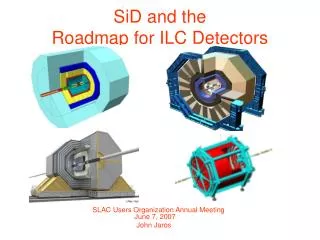
International Linear Collider The ILC requires 147m of 11.5mm period helical undulator (2007 design)
International Linear Collider + - • Undulator : • To produce a circularly polarised positron beam • High energy electron beam through helical undulator • emission of polarised photons. • Downstream high Z target, pair production • Positrons stripped off to produce polarised positron beam. Undulator Period 11.5 mm Field on Axis 0.86 T Peak field homogeneity <1% Winding bore >6mm Undulator Length 147 m Nominal current 215A Critical current ~270A Manufacturing tolerances winding concentricity 20µm winding tolerances 100µm straightness 100µm NbTi wire Cu:Sc ratio 0.9 Winding block 9 layers Ribbon 7 wire
Design drivers • Initial specification • Electron Drive Beam Energy 150 GeV • Photon Energy (1st harmonic ) 10.06 MeV • Photon Beam Power 131 kW • Total undulator length 100-200m • Undulator Period 11.6mm • Field on Axis 0.84 T • Beam Stay clear 4.5mm dia Graph of peak field against period for constant undulator K value.
Design specification Undulator Period 11.5 mm Field on Axis 0.86 T Peak field homogeneity <1% Winding bore >6mm Undulator Length 147 m Nominal current 215A Critical current ~270A Magnetic bore 6.35mm K 0.92 Manufacturing tolerances winding concentricity +/-20um winding periodicity +/-50um Axial straightness +/-50um NbTi wire Cu:Sc ratio 0.9 Winding block 9 layers 7 wire ribbon
Helical Undulator We made a number of short test pieces and ended up manufacturing wires into a cable to improve tolerance on windings
Manufacture One of the 2m sections after winding and potting Detail of windings View of the end superconducting connections
Assembly Undulator in helium bath which is in cryostat main body Two sections joined a the middle and mechanically anchored at that point.
Assembly • Turret has: • Cryocooler • Recondenser • HTS current lead assembly • Fill and vent ports
2m Module testing • 2m module mounted vertically in liquid helium bath • 2m carbon fibre rod with two hall probes mounted orthogonally to each other and undulator axis • Logging system controls a stepper motor to move the probe through the undulator and then take voltage readings from the two hall probes • Probes can be orientated in 8 directions (0, 45, 90, 135, 180, 225, 270, 315 deg)
2m Module testing • Each 2m module was tested in a cryostat • Field profile taken along the length every 0.1mm Graph of field against position along undulator Nick Ryder on top of cryostat
R(um) R(um) Helical beam purity Field profile Fourier analysed and plotted on a semi-logarithmic scale – sinewave is very pure – these are the same magnet with data taken on two different runs. Peak corresponds to 11.5mm period Particle trajectories using measured beam profile as calculated by SPECTRA as expected
Planar Undulator • Diamond light source can make use of a high performance planar undulator • Different geometry to the helical • Initial parameters are in table below • Aiming for good phase error in the external beam around 2-3°
Planar Undulator Cryogenics: Aim to run magnet at 1.8K Beam tube at around 12K
Planar Undulator Not good Better Winding trials within 10µm
Nb3Sn in Helical Undulator • We have an EuCARD Programme running to look at the use of Nb3Sn in helical undulators • Motivation: • Higher peak field • Possibly shorter undulator length • Temperature tolerance • “Simple” programme: • Source conductor • Use same period as for the NbTi undulator (11.5mm) • Wind test piece • Test • Report
Nb3Sn in Helical Undulator We have had the superconducting wire tested at Karlsuhe Institute of Technology and found (as we feared) that it is unstable at low fields: We have two samples tested which have undergone different heat treatment to assess influence of stabilising copper RRR
Nb3Sn in Helical Undulator Modelling using extrapolated low field values • Field strength and Ic at 1 kA. • Winding ID: Ø6.35 mm. • Field on axis: 1.54 T. (0.7T higher than NbTi undulator) • Peak field in conductor: 4.42 T. • Operating at 82% of Ic.
Nb3Sn in Helical Undulator • Challenges: • The wire suffers from “magneto thermal” instabilities: • Magnetisation instability – redistribution of persistent currents (depends on filament size) • Self Field instability – redistribution of the transport current within the conductor • Not clear that these problems can be overcome with current technology ... It turns out that the stability is worse with high critical current so it is not clear that a stable wire can be procured for this programme.
ColdDiag One of the key issues surrounding undulators is the amount of heat deposited in the beam tube from “Wakefield Heating” The beam passing through the beam tube is charged and this generates currents in the beam tube which generate Joule heating. Hope to install this experiment on Diamond late this year.
Summary • Where we are: • Results from the tests on the 4m helical look good • Working to address minor issues to achieve zero loss in cryostat • Planning tests to look at influence of wakefield heating on the magnet • Planar undulator development is challenging but if we can pull it off it will be a world beater • Nb3Sn development not looking too promising because of low field stability issues • Insulation system development continuing – important for a number of projects • Vital that it is thin for the use of Nb3Sn in the helical otherwise advantage over NbTi is quickly lost • Shows the advantage of working in close partnership over design and specification