Download
1 / 9
90 likes | 443 Views
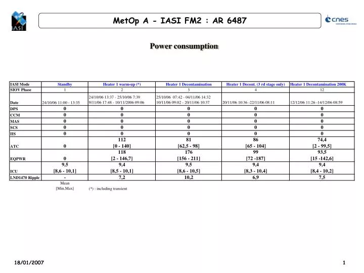
Power consumption. Power consumption. Power consumption. The power consumption determined with the in orbit HK is consistent with The optical vacuum results (IA-AR-1000-9858-AER) The IASI /METOP ICD (MO-IC-MMT-IA-0001, Issue 7). Thermal lines activation.

E N D
Power consumption • The power consumption determined with the in orbit HK is consistent with • The optical vacuum results (IA-AR-1000-9858-AER) • The IASI /METOP ICD (MO-IC-MMT-IA-0001, Issue 7)
Thermal lines activation • The heater lines of IASI are composed of : • 14 ATC lines for the thermal control of the instrument • 6 decontamination lines for the 300 and 200K decontamination of the radiator • 5 deployment lines for the CD, CCFD and LFDs deployment • Note : • The decontamination and deployments lines can not be switched on together • The decontamination lines are activated in the “Heater 1 Decontamination” mode in conjunction with the ATC (Warm-Up targets) • The deployment lines are activated individually (i.e. one by one) in the “Heater 1 deployment” mode in conjunction with the ATC (Warm-Up targets) • For all the higher modes, the ATC lines are activated in conjunction with the equipment switch on, at operational targets. • These lines are driven thanks to hardware automatons (one for the ATC, one for the Decontamination or Deployment activities)
ATC Thermal lines Impedance Decontamination Thermal lines Impedance
It is possible to establish the ripple on the EQPWR bus by injecting in the thermal simulation model the PWM and voltage acquired in the HK (4/11/06 09:37)
EQPWR Ripples simulation data for the Heater 1Warm-Up & Heater 1 Decontamination are : • Heater 1 Warm-Up : 7.3 A • Heater 1 decontamination @300 K : 10.3 A • Heater 1 decontamination @200K : 7.6A • For the higher modes, combination of the simulated ripple of the heater lines and ripple measured during AIT activities allow to establish the following table (ripple at frequency 1, 4.8 and 1/8 Hz): IASI Deviation Request (IA-DR-1000-1115-AER) is updated • To integrate the ripple in decontamination mode (300K) • To update the ripple value for other modes