Download
1 / 21
210 likes | 309 Views
Explore the crucial roles of I/O and processing in computers, focusing on I/O hardware, operating system functions, device control, and interface bridging. Learn about I/O subsystems, device drivers, and diverse I/O devices used in various computer systems.

E N D
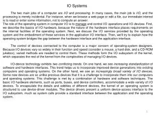
IO Systems The two main jobs of a computer are I/O and processing. In many cases, the main job is I/O, and the processing is merely incidental. For instance, when we browse a web page or edit a file, our immediate interest is to read or enter some information, not to compute an answer. The role of the operating system in computer I/O is to manage and control I/O operations and I/O devices. First, we describe the basics of I/O hardware, because the nature of the hardware interface places requirements on the internal facilities of the operating system. Next, we discuss the I/O services provided by the operating system and the embodiment of these services in the application I/O interface. Then, we’ll try to explain how the operating system bridges the gap between the hardware interface and the application interface. The control of devices connected to the computer is a major concern of operating-system designers. Because I/O devices vary so widely in their function and speed (consider a mouse, a hard disk, and a CD-ROM jukebox), varied methods are needed to control them. These methods form the I/O subsystem of the kernel, which separates the rest of the kernel from the complexities of managing I/O devices. I/O-device technology exhibits two conflicting trends. On one hand, we see increasing standardization of software and hardware interfaces. This trend helps us to incorporate improved device generations into existing computers and operating systems. On the other hand, we see an increasingly broad variety of I/O devices. Some new devices are so unlike previous devices that it is a challenge to incorporate them into our computers and operating systems. This challenge is met by a combination of hardware and software techniques. The basic I/O hardware elements, such as ports, buses, and device controllers, accommodate a wide variety of I/O devices. To encapsulate the details and oddities of different devices, the kernel of an operating system is structured to use device-driver modules. The device drivers present a uniform device-access interface to the I/O subsystem, much as system calls provide a standard interface between the application and the operating system.
Computers operate a great many kinds of devices. Most fit into the general categories of storage devices (disks, tapes), transmission devices (network cards, modems), and human-interface devices (screen, keyboard, mouse). Other devices are more specialized, such as the steering of a military fighter jet or a space shuttle. In these aircraft, a human gives input to the flight computer via a joystick and foot pedals, and the computer sends output commands that cause motors to move rudders, flaps, and thrusters. Despite the incredible variety of I/O devices, though, we need only a few concepts to understand how the devices are attached and how the software can control the hardware. A device communicates with a computer system by sending signals over a cable or even through the air. The device communicates with the machine via a connection point (or port) — for example, a serial port. If devices use a common set of wires, the connection is called a bus. A bus is a set of wires and a rigidly defined protocol that specifies a set of messages that can be sent on the wires. In terms of the electronics, the messages are conveyed by patterns of electrical voltages applied to the wires with defined timings. When device A has a cable that plugs into device B, and device B has a cable that plugs into device C, and device C plugs into a port on the computer, this arrangement is called a daisy chain. A daisy chain usually operates as a bus. Buses are used widely in computer architecture. A typical PC bus structure appears in Figure 1. This figure shows a PCI bus (the common PC system bus) that connects the processor—memory subsystem to the fast devices and an expansion bus that connects relatively slow devices such as the keyboard and serial and parallel ports. In the upper-right portion of the figure, four disks are connected together on a SCSI bus plugged into a SCST controller. A controller is a collection of electronics that can operate a port, a bus, or a device. A serial-port controller is a simple device controller. It is a single chip (or portion of a chip) in the computer that controls the signals on the wires of a serial port. By contrast, a SCSI bus controller is not simple. Because the SCSI protocol is complex, the SCSI bus controller is often implemented as a separate circuit board (or a host adapter) that plugs into the computer. It typically contains a processor, microcode, and some private memory to enable it to process the SCSI protocol messages. Some devices have their own built-in controllers. If you look at a disk drive, you will see a circuit board attached to one side. This board is the disk controller. It implements the disk side of the protocol for some kind of connection—SCSI or ATA, for instance. It has microcode and a processor to do many tasks, such as bad-sector mapping, pre-fetching, buffering, and caching.
Figure 1. A typical PC bus structure How can the processor give commands and data to a controller to accomplish an I/O transfer? The short answer is that the controller has one or more registers for data and control signals. The processor communicates with the controller by reading and writing bit patterns in these registers. One way in which this communication can occur is through the use of special I/O instructions that specify the transfer of a byte or word to an I/O port address. The I/O instruction triggers bus lines to select the proper device and to move bits “into or out of a device register”. Alternatively, the device controller can support memory-mapped I/O. In this case, the device-control registers are mapped into the address space of the processor. The CPU executes I/O requests using the standard data-transfer instructions to read and write the device-control registers. Some systems use both techniques. For instance, PCs use I/O instructions to control some devices and memory-mapped I/O to control others.
Figure 2 shows the usual I/O port addresses for PCs. The graphics controller has I/O ports for basic control operations, but the controller has a large memory-mapped region to hold screen contents. The process sends output to the screen by writing data into the memory-mapped region. The controller generates the screen image based on the contents of this memory. This technique is simple to use. Moreover, writing millions of bytes to the graphics memory is faster than issuing millions of I/O instructions. Figure 2. Devices IO port locations on PC But the ease of writing to a memory-mapped I/O controller is offset by a disadvantage. Because a common type of software fault is a write through an incorrect pointer to an unintended region of memory, a memory-mapped device register is vulnerable to accidental modification. Of course, protected memory helps to reduce this risk. An I/O port typically consists of four registers, called the (1) status, (2) control, (3) data-in, and (4) data-out registers.
• The data-in register is read by the host to get input. • The data-out register is written by the host to send output. • The status register contains bits that can be read by the host. These bits indicate states, such as whether the current command has completed, whether a byte is available to be read from the data-in register, and whether a device error has occurred. • The control register can be written by the host to start a command or to change the mode of a device. For instance, a certain bit in the control register of a serial port chooses between full-duplex and half-duplex communication, another bit enables parity checking, a third bit sets the word length to 7 or 8 bits, and other bits select one of the speeds supported by the serial port. The data registers are typically 1 to 4 bytes in size. Polling The complete protocol for interaction between the host arid a controller can be intricate, but the basic handshaking notion is simple. We explain handshaking with an example. We assume that 2 bits are used to coordinate the producer-consumer relationship between the controller and the host. The controller indicates its state through the busy bit in the status register. (Recall that to set a bit means to write a 1 into the bit and to clear a bit means to write a 0 into it.) The controller sets the busy bit when it is busy working and clears the busy bit when it is ready to accept the next command. The host signals its wishes via the command-ready bit in the command register. The host sets the command-ready bit when a command is available for the controller to execute. For this example, the host writes output through a port, coordinating with the controller by handshaking as follows: 1. The host repeatedly reads the busy bit until that bit becomes clear. 2. The host sets the write bit in the command register and writes a byte into the data-out register. 3. The host sets the command-ready bit. 4. When the controller notices that the command-ready bit is set, it sets the busy bit. 5. The controller reads the command register and sees the write command. It reads the data-out register to get the byte and does the I/O to the device. 6. The controller clears the command-ready bit, clears the error bit in the status register to indicate that the device I/O succeeded, and clears the busy bit to indicate that it is finished.
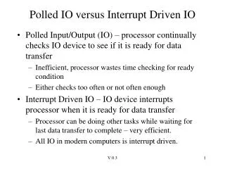
This loop is repeated for each byte. In step 1, the host is busy-waiting or polling: It is in a loop, reading the status register over and over until the busy bit becomes clear. If the controller and device are fast, this method is a reasonable one. But if the wait may be long, the host should probably switch to another task. How, then, does the host know when the controller has become idle? For some devices, the host must service the device quickly, or data will be lost. For instance, when data are streaming in on a serial port or from a keyboard, the small buffer on the controller will overflow' and data will be lost if the host waits too long before returning to read the bytes. In many computer architectures, three CPU-instruction cycles are sufficient to poll a device: read a device register, logical—and to extract a status bit, and branch if not zero. Clearly, the basic polling operation is efficient. But polling becomes inefficient when it is attempted repeatedly yet rarely finds a device to be ready for service, while other useful CPU processing remains undone. In such instances, it may be more efficient to arrange for the hardware controller to notify the CPU when the device becomes ready for service, rather than to require the CPU to poll repeatedly for an I/O completion. The hardware mechanism that enables a device to notify the CPU is called an interrupt. Interrupts The basic interrupt mechanism works as follows. The CPU hardware has a wire called the interrupt-request line that the CPU senses after executing every instruction. When the CPU detects that a controller has asserted a signal on the interrupt request line, the CPU performs a state save and jumps to the interrupt-handler routine at a fixed address in memory. The interrupt handler determines the cause of the interrupt, performs the necessary processing, performs a state restore, and executes a return from interrupt instruction to return the CPU to the execution state prior to the interrupt. We say that the device controller raises an interrupt by asserting a signal on the interrupt request line, the CPU catches the interrupt and dispatches it to the interrupt handler, and the handler clears the interrupt by servicing the device. Figure 3 summarizes the interrupt-driven I/O cycle.
Figure 3. Interrupt driven I/O cycle • This basic interrupt mechanism enables the CPU to respond to an asynchronous event, as when a device controller becomes ready for set-vice. In a modern operating system, however, we need more sophisticated interrupt-handling features. • 1. We need the ability to defer interrupt handling during critical processing. • We need an efficient way to dispatch to the proper interrupt handler for a device without first polling all the devices to see which one raised the interrupt. • We need multilevel interrupts, so that the operating system can distinguish between high and low-priority interrupts and can respond with the appropriate degree of urgency.
In modern computer hardware, these three features are provided by the CPU and by the interrupt-controller hardware. Most CPUs have two interrupt request lines. One is the nonmaskable interrupt, which is reserved for events such as unrecoverable memory errors. The second interrupt line is maskable: It can be turned off by the CPU before the execution of critical instruction sequences that must not be interrupted. The maskable interrupt is used by device controllers to request service. The interrupt mechanism accepts an address - a number that selects a specific interrupt-handling routine from a small set. In most architectures, this address is an offset in a table called the interrupt vector. This vector contains the memory addresses of specialized interrupt handlers. The purpose of a vectored interrupt mechanism is to reduce the need for a single interrupt handler to search all possible sources of interrupts to determine which one needs service. In practice, however, computers have more devices (and, hence, interrupt handlers) than they have address elements in the interrupt vector. A common way to solve this problem is to use the technique of interrupt chaining, in which each element in the interrupt vector points to the head of a list of interrupt handlers. When an interrupt is raised, the handlers on the corresponding list are called one by one, until one is found that can service the request. This structure is a compromise between the overhead of a huge interrupt table and the inefficiency of dispatching to a single interrupt handler. Figure 4 illustrates the design of the interrupt vector for the Intel Pentium processor. The events from 0 to 31, which are nonmaskable, are used to signal various error conditions. The events from 32 to 255, which are maskable, are used for purposes such as device-generated interrupts. The interrupt mechanism also implements a system of interrupt priority levels. This mechanism enables the CPU to defer the handling of low-priority interrupts without masking off all interrupts and makes it possible for a high-priority interrupt to preempt the execution of a low-priority interrupt. A modern operating system interacts with the interrupt mechanism in several ways. At boot time, the operating system probes the hardware buses to determine what devices are present and installs the corresponding interrupt handlers into the interrupt vector. During I/O, the various device controllers raise interrupts when they are ready for service. These interrupts signify that output has completed, or that input data are available, or that a failure has been detected. The interrupt mechanism is also used to handle a wide variety of exceptions, such as dividing by zero, accessing a protected or nonexistent memory address, or attempting to execute a privileged instruction from user mode. The events that trigger interrupts have a common property: They are occurrences that induce the CPU to execute an urgent, self-contained routine.
An operating system has other good uses for an efficient hardware and software mechanism that saves a small amount of processor state and then calls a privileged routine in the kernel. For example, many operating systems use the interrupt mechanism for virtual memory paging. A page fault is an exception that raises an interrupt. The interrupt suspends the current process and jumps to the page-fault handler in the kernel. This handler saves the state of the process, moves the process to the wait queue, performs page-cache management, schedules an I/O operation to fetch the page, schedules another process to resume execution, and then returns from the interrupt. Another example is found in the implementation of system calls. Usually a program uses library calls to issue system calls. The library routines check the arguments given by the application, build a data structure to convey the arguments to the kernel, and then execute a special instruction called a software interrupt (or a trap). This instruction has an operand that identifies the desired kernel service. When a process executes the trap instruction, the interrupt hardware saves the state of the user code, switches to supervisor mode, and dispatches to the kernel routine that implements the requested service. The trap is given a relatively low interrupt priority compared with those assigned to device interrupts - executing a system call on behalf of an application is less urgent than servicing a device controller before its FIFO queue overflows and loses data. Direct Memory Access For a device that does large transfers, such as a disk drive, it seems wasteful to use an expensive general-purpose processor to watch status bits and to feed data into a controller register one byte at a time — a process termed programmed I/O (PIO). Many computers avoid burdening the main CPU with PIO by offloading some of this work to a special-purpose processor called a direct-memory-access (DMA) controller. To initiate a DMA transfer, the host writes a DMA command block into memory. This block contains a pointer to the source of a transfer, a pointer to the destination of the transfer, and a countof the number of bytes to be transferred. The CPU writes the address of this command block to the DMA controller, then goes on with other work. The DMA controller proceeds to operate the memory bus directly, placing addresses on the bus to perform transfers without the help of the main CPU. A simple DMA controller is a standard component in PCs, and bus-mastering I/O boards for the PC usually contain their own high-speed DMA hardware.
Handshaking between the DMA controller and the device controller is performed via a pair of wires called DMA- request and DMA-acknowledge. The device controller places a signal on the DMA request wire when a word of data is available for transfer. This signal causes the DMA controller to seize the memory bus, to place the desired, address on the memory-address wires, and to place a signal on the DMA —acknowledge wire. When the device controller receives the DMA —acknowledge signal, it transfers the word of data to memory and removes the DMA —request signal. Figure 5. Steps in DMA transfer When the entire transfer is finished, the DMA controller interrupts the CPU. This process is depicted in Figure 5. When the DMA controller seizes the memory bus, the CPU is momentarily prevented from accessing main memory, although it can still access data items in its primary and secondary caches. Although this cycle stealing can slow down the CPU computation, offloading the data-transfer work to a DMA controller generally improves the total system performance. Some computer architectures use physical memory addresses for DMA, but others perform direct virtual memory access (DVMA), using virtual addresses that undergo translation to physical addresses. DVMA can perform a transfer between two memory-mapped devices without the intervention of the CPU or the use of main memory.
Application I/O Interface In this section, we discuss structuring techniques and interfaces for the operating system that enable I/O devices to be treated in a standard, uniform way. We explain, for instance, how an application can open a file on a disk without knowing what kind of disk it is and how new disks and other devices can be added to a computer without disruption of the operating system. Like other complex software-engineering problems, the approach here involves abstraction, encapsulation, and software layering. Specifically, we can abstract away the detailed differences in I/O devices by identifying a few general kinds. Each general kind is accessed through a standardized set of functions — an interface. The differences are encapsulated in kernel modules called device drivers that internally are custom-tailored to each device but that export one of the standard interfaces. Figure 6 illustrates how the I/O-related portions of the kernel are structured in software layers. Figure 6. A kernel I/O structure
The purpose of the device-driver layer is to hide the differences among device controllers from the I/O subsystem of the kernel, much as the I/O system calls encapsulate the behavior of devices in a few generic classes that hide hardware differences from applications. Making the I/O subsystem independent of the hardware simplifies the job of the operating-system developer. It also benefits the hardware manufacturers. They either design new devices to be compatible with an existing host controller interface (such as SCSI-2), or they write device drivers to interface the new hardware to popular operating systems. Thus, we can attach new peripherals to a computer without waiting for the operating-system vendor to develop support code. Unfortunately for device-hardware manufacturers, each type of operating system has its own standards for the device-driver interface. A given device may ship with multiple device drivers - for instance, drivers for MS-DOS, Windows 95/98, Windows NT/2000, and Solaris. Devices vary on many dimensions, as illustrated in Figure 7. Figure 7. Characteristics of I/O devices
Character-stream or block. A character-stream device transfers bytes one by one, whereas a block device transfers a block of bytes as a unit. Sequential or random-access. A sequential device transfers data in a fixed order determined by the device, whereas the user of a random-access device can instruct the device to seek to any of the available data storage locations. Synchronous or asynchronous. A synchronous device performs data transfers with predictable response times. An asynchronous device exhibits irregular or unpredictable response times. Sharable or dedicated. A sharable device can be used concurrently by several processes or threads; a dedicated device cannot. Speed of operation. Device speeds range from a few bytes per second to a few gigabytes per second. Read-write, read only, or write only. Some devices perform both input and output, but others support only one data direction. For the purpose of application access, many of these differences are hidden by the operating system, and the devices are grouped into a few conventional types. The resulting styles of device access have been found to be useful and broadly applicable. Although the exact system calls may differ across operating systems, the device categories are fairly standard. The major access conventions include block I/O, character-stream I/O, memory-mapped file access, and network sockets. Operating systems also provide special system calls to access a few additional devices, such as a time-of-day clock and a timer. Some operating systems provide a set of system calls for graphical display, video, and audio devices. Most operating systems also have an escape (or back door) that transparently passes arbitrary commands from an application to a device driver. In UNIX, this system call is ioctl() (for "I/O" control). The ioctl() system call, enables an application to access any functionality that can be implemented by any device driver, without the need to invent a new system call. The ioctl() system call has three arguments. The first is a file descriptor that connects the application to the driver by referring to a hardware device managed by that driver. The second is an integer that selects one of the commands implemented in the driver. The third is a pointer to an arbitrary data structure in memory that enables the application and driver to communicate any necessary control information or data.
Block and Character Devices The block-device interface captures all the aspects necessary for accessing disk drives and other block-oriented devices. The device is expected to understand commands such as read() and write(); if it is a random-access device, it is also expected to have a seek() command to specify which block to transfer next. Applications normally access such a device through a file-system interface. We can see that read(), write (), and seek() capture the essential behaviors of block-storage devices, so that applications are insulated from the low-level differences among those devices. The operating system itself, as well as special applications such as database-management systems, may prefer to access a block device as a simple linear array of blocks. This mode of access is sometimes called raw I/O. If the application performs its own buffering, then using a file system would cause extra, unneeded buffering. Likewise, if an application provides its own locking of file blocks or regions, then any operating-system locking services would be redundant at the least and contradictory at the worst. To avoid these conflicts, raw-device access passes control of the device directly to the application, letting the operating system step out of the way. Unfortunately, no operating-system-services are then performed on this device. A compromise that is becoming common is for the operating system to allow a mode of operation on a file that disables differing and locking. In the UNIX world, this is called direct I/O. A keyboard is an example of a device that is accessed through a character-stream interface. The basic system calls in this interface enable an application to get() or put() one character. On top of this interface, libraries can be built that offer line-at-a-time access, with buffering and editing services (for example, when a user types a backspace, the preceding character is removed from the input stream). This style of access is convenient for input devices such as keyboards, mice, and modems that produce data for input "spontaneously" — that is, at times that cannot necessarily be predicted by the application. This access style is also good for output devices such as printers and audio boards, which naturally fit the concept of a linear stream of bytes.
Network Devices Because the performance and addressing characteristics of network I/O differ significantly from those of disk I/O, most operating systems provide a network I/O interface that is different from the read()-write() -seek() interface used for disks. One interface available in many operating systems, including UNIX and Windows NT, is the network socket interface. Think of a wall socket for electricity: Any electrical appliance can be plugged in. By analogy, the system calls in the socket interface enable an application to create a socket, to connect a local socket to a remote address (which plugs this application into a socket created by another application), to listen for any remote application to plug into the local socket, and to send and receive packets over the connection. To support the implementation of servers, the socket interface also provides a function called select() that manages a set of sockets. A call to select() returns information about which sockets have a packet waiting to be received and which sockets have room to accept a packet to be sent. The use of select () eliminates the polling and busy waiting that would otherwise be necessary for network I/O. These functions encapsulate the essential behaviors of networks, greatly facilitating the creation of distributed applications that can use any underlying network hardware and protocol stack. Many other approaches to interprocess communication and network communication have been, implemented. For instance, Windows NT provides one interface to the network interface card and a second interface to the network protocols. In UNIX, which has a long history as a proving ground for network technology, we find half-duplex pipes, full-duplex FIFOs, full-duplex STREAMS, message queues, and sockets. Clocks and Timers Most computer's have hardware clocks and timers that provide three basic functions: • Give the current time. • Give the elapsed time. • Set a timer to trigger operation X at time T. These functions are used heavily by the operating system, as well as by time-sensitive applications. Unfortunately, the system calls that implement these functions are not standardized across operating systems.
The hardware to measure elapsed time and to trigger operations is called a programmable interval timer. It can be set to wait a certain amount of time and then generate an interrupt, and it can be set to do this once or to repeat the process to generate periodic interrupts. The scheduler uses this mechanism to generate an interrupt that will preempt a process at the end of its time slice. The disk I/O subsystem uses it to invoke the flushing of dirty cache buffers to disk periodically, and the network subsystem uses it to cancel operations that are proceeding too slowly because of network congestion or failures. The operating system may also provide an interface for user processes to use timers. The operating system can support more timer requests than the number of timer hardware channels by simulating virtual clocks. To do so, the kernel (or the timer device driver) maintains a list of interrupts wanted by its own routines and by user requests, sorted in earliest-time-first order. It sets the timer for the earliest time. When the timer interrupts, the kernel signals the requester and reloads the timer with the next earliest time. Blocking and Non-blocking IO Another aspect of the system-call interface relates to the choice between blocking I/O and non-blocking I/O. When an application issues a blocking system call, the execution of the application is suspended. The application is moved from the operating system's run queue to a wait queue. After the system call completes, the application is moved back to the run queue, where it is eligible to resume execution, at which time it will receive the values returned by the system call. The physical actions performed by I/O devices are generally asynchronous - they take a varying or unpredictable amount of time. Nevertheless, most operating systems use blocking system calls for the application interface, because blocking application code is easier to understand than nonblocking application code. Some user-level processes need nonblocking I/O. One example is a user interface that receives keyboard and mouse input while processing and displaying data on the screen. Another example is a video application that reads frames from a file on disk while simultaneously decompressing and displaying the output on the display. One way an application writer can overlap execution with I/O is to write a multithreaded application. Some threads can perform blocking system calls, while others continue executing. The Solaris developers used this technique to implement a user-level library for asynchronous I/O, freeing the application writer from that task. Some operating systems provide nonblocking I/O system calls. A nonblocking call does not halt the execution of the application for an extended time. Instead, it returns quickly, with a return value that indicates how many bytes were transferred.
An alternative to a nonblocking system call is an asynchronous system call. An asynchronous call returns immediately, without waiting for the I/O to complete. The application continues to execute its code. The completion of the I/O at some future time is communicated to the application, either through the setting of some variable in the address space of the application or through the triggering of a signal or software interrupt or a call-back routine that is executed outside the linear control flow of the application. The difference between .nonblocking and asynchronous system calls is that a nonblocking read() returns immediately with whatever data are available - the full number of bytes requested, fewer, or none at all. An asynchronous read() call requests a transfer that will be performed in its entirety but that will complete at some future time. These two I/O methods are shown in Figure 8. Figure 8. Two I/O methods a) synchronous b) asynchronous
Kernel I/O Subsystem Kernels provide many services related to I/O. Several services - scheduling, buffering, caching, spooling, device reservation, and error handling - are provided by the kernel's I/O subsystem and build on the hardware and device-driver infrastructure. The I/O subsystem is also responsible for protecting itself from errant processes and malicious users. I/O Scheduling To schedule a set of I/O requests means to determine a good order in which to execute them. The order in which applications issue system calls rarely is the best choice. Scheduling can improve overall system performance, can share device access fairly among processes, and can reduce the average waiting time for I/O to complete. Here is a simple example to illustrate the opportunity. Suppose that a disk arm is near the beginning of a disk and that three applications issue blocking read calls to that disk. Application 1 requests a block near the end of the disk, application 2 requests one near the beginning, and application 3 requests one in the middle of the disk. The operating system can reduce the distance that the disk arm. travels by serving the applications in the order 2, 3, 1. Rearranging the order of service in this way is the essence of I/O scheduling. Operating-system developers implement scheduling by maintaining a wait queue of requests for each device. When an application issues a blocking I/O system call, the request is placed on the queue for that device. The I/O scheduler rearranges the order of the queue to improve the overall system efficiency and the average response time experienced by applications. The operating system may also try to be fair, so that no one application receives especially poor service, or it may give priority service for delay-sensitive requests. When a kernel supports asynchronous I/O, it must be able to keep track of many I/O requests at the same time. For this purpose, the operating system might attach the wait queue to a. device-status table. The kernel manages this table, which contains an entry for each I/O device, as shown in Figure 9. Each table entry indicates the device's type, address, and state (not functioning, idle, or busy). If the device is busy with a request, the type of request and other parameters will be stored in the table entry for that device. One way in which the I/O subsystem improves the efficiency of the computer is by scheduling I/O operations. Another way is by using storage space in main memory or on disk via techniques called buffering, caching, and spooling.
Figure 9. Device status table Buffering Buffering is also an issue for both block and character devices. For block devices, the hardware generally insists upon reading and writing entire blocks at once, but user processes are free to read and write in arbitrary units. If a user process writes half a block, the operating system will normally keep the data around internally until the rest of the data are written, at which time the block can go out to the disk. For character devices, users can write data to the system faster than it can be output, necessitating buffering. Keyboard input that arrives before it is needed also requires buffering.
Error Reporting Errors are far more common in the context of I/O than in any other context. When they occur, the operating system must handle them as best it can. Many errors are device-specific, so only the driver knows what to do (e.g., retry, ignore, or panic). A typical error is caused by a disk block that has been damaged and cannot be read any more. After the driver has tried to read the block a certain number of times, it gives up and informs the device-independent software. How the error is treated from here on is device independent. If the error occurred while reading a user file, it may be sufficient to report the error back to the caller. However, if it occurred while reading a critical system data structure, such as the block containing the bitmap showing which blocks are free, the operating system may have to display an error message and terminate. Allocating and Releasing Dedicated Devices Some devices, such as CD-ROM recorders, can be used only by a single process at any given moment. It is up to the operating system to examine requests for device usage and accept or reject them, depending on whether the requested device is available or not. A simple way to handle these requests is to require processes to perform opens on the special files for devices directly. If the device is unavailable, the open fails. Closing such a dedicated device then releases it. Device-Independent Block Size Not all disks have the same sector size. It is up to the device-independent software to hide this fact and provide a uniform block size to higher layers, for example, by treating several sectors as a single logical block. In this way, the higher layers only deal with abstract devices that all use the same logical block size, independent of the physical sector size. Similarly, some character devices deliver their data one byte at a time (e.g., modems), while others deliver theirs in larger units (e.g., network interfaces). These differences may also be hidden.