Download
1 / 40
400 likes | 607 Views
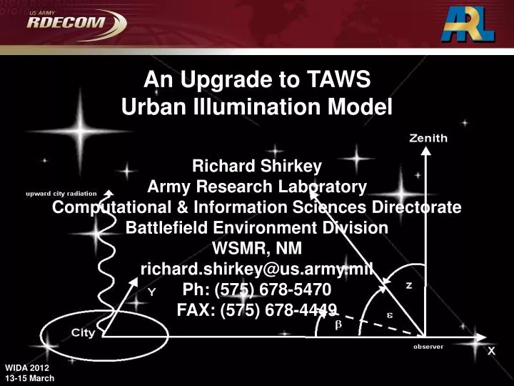
An Upgrade to TAWS Urban Illumination Model . Richard Shirkey Army Research Laboratory Computational & Information Sciences Directorate Battlefield Environment Division WSMR, NM richard.shirkey@us.army.mil Ph: (575) 678-5470 FAX: (575) 678-4449. WIDA 2012 13-15 March. OUTLINE. Purpose

E N D
An Upgrade to TAWS Urban Illumination Model Richard Shirkey Army Research Laboratory Computational & Information Sciences Directorate Battlefield Environment Division WSMR, NM richard.shirkey@us.army.mil Ph: (575) 678-5470 FAX: (575) 678-4449 WIDA 2012 13-15 March
OUTLINE • Purpose • Beginnings • Walker • Treanor • Objective • Garstang’s improvements • AIM v2 • Spectral Radiance • V&V
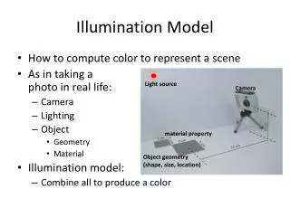
Purpose • To provide urban illumination levels for use in/for • Simulations • IWARS • Target Acquisition • TAWS • Night Vision Devices
Beginnings: Walker’s Model 3.0 Population x 106 2.0 1.0 20 40 60 80 100 Distance (miles) Walker took sky brightness measurements of various cities to determine the distance where the artificial sky brightness was 0.1 mag at the zenith. From this he constructed the first Population-Distance relation. Garstang reformulated Walker’s P-D relation as B = CPD-2.5. Known as Walker’s law, it is the simplest model for light pollution. C does not depend on P and D, but depends on factors such as the light emission per head of the population and the reflectivity of the ground
Beginnings: Treanor’s Model Treanor proposed a simple model for scattering along the direct beam (TZ) by restricting scattering to a small angle m. This restricts scattering to the particles which are contained within the figure of revolution generated by rotating the arc TQZ about TZ. This scattered light then undergoes a final scattering at Z into the observer’s LOS. when ' > mscattering is not considered
Objective • A quick running model that accurately portrays both broadband and spectral illumination received from urban sources by an arbitrarily placed observer • point source • observer 2.25 x city radius • extended source • observer 2.25 x city radius • internal to the city • Easily obtainable inputs • Atmospheric variables • aerosols • clouds : acceptable error D: distance to source R: radius of source E: irradiance L': radiance Eex = πL'R 2 / (R 2 + D 2) Ept = πL'R 2 / D 2 = (Ept – Eex)/Eex = R2/D2 D R -½ ( 20% D 2.25 R) criterion
© International Dark-Sky Association Garstang’s Model Assumptions for Garstang’s model are: • Flat Earth • All downward-directed light from • fixtures does not undergo scattering or • absorption wrt the atmosphere • No interaction with buildings or vegetation • Aerosol scattering is predominantly in the forward direction
Garstang’s Model Garstang further modified Treanor’s model by introducing an exponential atmosphere and directly relating the atmospheric molecular content to the aerosol content Naa = 11.11 Nm m K e-cH where N is the number density, is the particle cross section, H is the height of the city and K is Garstang’s “clarity factor”.
Garstang’s Model The city emission function is defined by I = LP/2 {2G (1-F) cos + 0.554 F 4} City Emission Function • where I is the upward intensity, F is the fraction of light that “escapes” the luminaries shielding in an upward direction, G is the surface albedo and • is the angle between the upward normal and an upward light ray. • Cinzano has found that the shape of the emission function is not important
“Double Scattering” General Scenario Final Equations Brightness Small Angle Approximation
Garstang’s Model: Details Broadband Brightness in Garstang’s model is represented by x b = Nm R e-cH (dx dy / R2) du 0 Iup S-2 EFxq EFqo SAA { e-ch (1 + cos2[ + ]) 3/(16) + e-ah 11.11 K f( + )}
AIM v2 • Original model tenets maintained • brightness ~ population • SSA • City population data base included • Cloud effects added • 8 cloud types • reflection • Lighting data base added • Airglow included
Natural Background Radiation In the absence of moonlight and artificial light, the night sky still is not “dark”. S10 is a bizarre astronomical unit of surface brightness corresponding to one 10th-magnitude star per square degree
Natural Background Radiation In general: Bnsb = 27.78 – 2.5 x log10(Bairglow + Bzodiacal + Bstarlight), where Bairglow, Bzodiacal, and Bstarlight are functions of the solar sunspot cycle, the ecliptic latitude, and the galactic latitude respectively. It was deemed reasonable to set the value of Bnsb = 17.6 nL rather than carry out additional computations for only a small additional contribution to the total night sky brightness For Denver at a distance of ~70 km the model predicts that the brightness is ~18 nL.
Cloud Effects • Transmission through clouds determined using ILLUMA • 8 cloud types in 3 layers • High - clear, thin and thick Ci/Cs • Medium - clear, As/Ac • Low - clear, clear (f/k), Cu/Cb or St/Sc • allowance for partial cloudiness • Cloud reflection • cloud and angle dependent reflectivitytaken from Shaprio • simple attenuation in upward and downward paths • from lowest layer only
AIM Input • city name, city radius, city altitude, lumens/head • distance from observer to source, observer altitude, zenith angle, azimuth angle • clarity factor, surface albedo, fraction of light in upward direction • month, day, year, UTC • light type percents • cloud type & cloud amount for layer i, i = 1,3
Validation Clear Skies Sky brightness due to Denver as a function of zenith angle at a distance of 40 km* Sky brightness due to Denver as a function of distance for a zenith angle of zero* * Garstang ‘86
Brightness Distribution Denver 8.6 km from city center Zenith = 0 X Observer
Brightness Distribution Boulder Zenith = 65 Azimuth = 180 Distance = 0 km Boulder Zenith = 65 Azimuth = 0 Distance = 0 km X X Boulder Zenith = 65 Azimuth = 45 Distance = 0 km Boulder Zenith = 65 Azimuth = 45 Distance = 2 km X X X marks observer position
Spectral Radiant Energy Broadband illumination is broken into spectral components dependant on the City’s light types and amounts • Approach • Determine • Light types • Percent contribution • Spectral radiance values for each light type
Spectral Radiant Energy Light Types and their default percentages* * El Paso Electric Co.
Light Type Spectra (1 nm resolution) HPS Mercury Vapor LPS Metal Halide Fluorescent LED Propane Kerosene Incandescent
Spectral Radiant Energy Technique • For Light Type i • Identify total contribution over wavelength band • S1 to S2 • Bin contribution S1 S2 wavelength band under consideration HPS HPS
Spectral Radiant Energy Technique • Fractional radiance • Final spectral radiance • sum over light type
Spectral Radiance Spectrum of Los Angles Zenith view Courtesy of Dr. Martin Aubé http://lightpollution.no-ip.org/~lightpol/data_usage.html
Aubé AIM v2 10% Clear Mercury 5% LPS 55% HPS 20% Metal Halide 10% Incandescent No Airglow
Aubé AIM v2 10% Clear Mercury 5% LPS 55% HPS 20% Metal Halide 10% Incandescent SAB + Airglow Note increase in background level
V&V Night Illumination Test Evaluation (NITE) A Joint Undertaking with the UK Met Office
Night Illumination Test Evaluation (NITE) x
Night Illumination Test Evaluation (NITE) Shuttle Taxiway x
NITE: Instrumentation Microtops Sunphotometer 5 channel hand-held sunphotometer for measuring aerosol optical thickness easily, accurately and dependably.
NITE: Instrumentation LMT Hoffman Albedo stand All-Sky camera first day out (brrr)
NITE: Meteorology • Met data • WSMR04 • Holloman AFB • mesonetwest.utah.edu
What’s Next? • Variable turbid atmosphere • add assortment of aerosol types • Inclusion of horizontal single scattering effects • zenith angles > 80 produce dubious results • City reflection from partially cloudy skies • reflection only allowed from lowest layer • Terrain/Vegetation blocking • NITE data reduction for V&V
Acknowledgements Warren Lewis* (for suggesting NITE) Damian Wilson* (for tolerating numerous snafus) Jeff Passner§ (for satellite pics) Ed Creegan§ (for setup and data acquisition) Will Lee-Rodgers* (for just about everything else) * UKMO § ARL