Download

1 / 27
270 likes | 396 Views
Using Surfcam to Produce a Numeric Control (NC) Program. Production of Wheel Blanks for the Wooden Toy Project An Introduction to the CAD/CAM Process Instructions for 3 Axis Programming Using the D&M CNC Milling Machine and Cyclone Router.

E N D
Using Surfcam to Produce a Numeric Control (NC) Program Production of Wheel Blanks for the Wooden Toy Project An Introduction to the CAD/CAM Process Instructions for 3 Axis Programming Using the D&M CNC Milling Machine and Cyclone Router
The CAD/CAM process consists of the following steps: • The production of a drawing using a CAD program. • The identification of the types of cuts to be made and the sequence of the cuts (NC). • The Post Processing that converts the tool path sequences into G-Codes for use by the machine. • Making the part on the machine.
To produce the program for the wheel blanks for this exercise you will need to follow these general procedures: Create a 2d drawing using SolidWorks. Draw the wheels with a diameter ¼”greater than the wheel required (compensation for the bit diameter). Include the material perimeter in the drawing keeping any wheel circumference at least 1/8” from the material perimeter and each other Save the drawing as a .DXF file. Save the .DXF file on a flash drive. Open the file on a computer running the Surfcam software. Follow the steps listed on the following pages.
Surfcam Instructions Open Surfcam from the desktop on the laptop computer. Insert the flash drive into the laptop. Open the file that you need to have converted to G-code by selecting the location, file and file type. Be sure to have “AutoCAD DXF Files(*DXF) selected as “Files of type:”.
The following settings need to be made for converting the 2d .DXF data to Surfcam data.
The converted DXF data will appear as shown below. Select “Zoom Out” multiple times until the axis orientation marker, the origin point and the drawing data is shown on the screen together.
You will need to delete the extraneous data that has been placed on the diagram. To do this, select “Edit”, “Delete”, “Within” and use the cursor to surround the excess lines/text. Select “Cancel” when finished.
The drawing data will now need to be attached to the program origin. To move the drawing data, select; “Edit”, “Transform” & “Move”. Next, select “Location”. Then, select “Within”.
Click, drag and surround the drawing data. Select “Sketch”, click on the lower left-hand corner of the drawing data and then click directly on the origin point. The drawing data will now be attached to the origin and the diagram will need to be resized to fit the screen. To do this select “Display” & “Fit”.
Points for indicating where holes are to be drilled will need to be located on the diagram. To do this select “Create”, “Point” and “Center”. Touch the cursor to each of the circles to produce the center points. Select “Cancel” when finished. To begin producing the tool paths: Select NC 2-axis contour auto visible done Center points in place.
The holes will need to be drilled first in the sequence of cuts that are to be made. To program the drilling of the holes, select “NC”, “2-Axis” and “Drill”. Have “Single “ highlighted and then touch off on each of the center points. Select “Done” when the center points are highlighted.
The “Hole Processing“ dialogue box will appear. Change “Coolant” to “Off”. Select “Select Tool”.
Select “Drill” from the drill bit icons. Scroll through the list and select the ¼” HSS drill (#151). Select “OK”.
Select “Cycle Control” and set the “Hole Depth” to THE DEPTH REQUIRED BY YOUR PROJECT DESIGN. Use .55” to drill all the way through . Use .375” to drill ¾ of the way through the wheel blank. Select “OK”.
The diagram will now show the “Tool Path” in green. To see the depth of cut, select “View” and double click on “Isometric view”. The view can later be changed back to a top view by selecting “View” and double clicking on “TOP view”.
The contour cutting of the wheel outline will now need to be completed. Select “NC” from the menu and then, “2 Axis” and “Contour” . Select “Single” and highlight each of the circles. Select “Done” when the circles are highlighted.
Choose “Select Tool” and set the cutter as a 2-flute, 1/4” End Mill”. Choose “Select Material” and set the material as “Mahogany”. Set the “Feed Rate” at 50 and the “Plunge Rate” at 10. Select “Cut Control”. In the “Cut Control” dialogue box, set the “Amount to Remove” at .55” Set the “Rough Spacing” to 0 and .2” . Select “OK” twice.
The contouring tool paths are now complete. The next steps will produce the G-Code for the machine to run.
Once you have the NC process data in place, “Save” your file to the flash drive. Exit from the Surfcam software. Up until now you have been running the the “demonstration mode”. At this point you will need to insert the “software key” so that you may continue your work using the full capabilities of the software. Open Surfcam again. Open your file. Go to the operations manager, right click on the NC project And select “regenerate all”.
The material size data will now need to be entered. Right click on “NC Project” in the “Operations Manager” outline. In the sub-menu that appears select “Edit Setup Information”.
In the “Section Information” dialogue box select “Stock”. “Corner 1” is the lower, front, left corner of the material. “Corner 2” is the top, back, right corner of the material. Enter the data shown to the right for this project. Be sure to indicate the “Z” data for “Corner 1” as a negative number. Once the data is entered, select “Add” and then “OK”. -.55
Save the program at this point. Select “Toolpath Verification” to inspect the program that has been created.
The “Toolpath Verification” screen will appear. Move the “speed control” slider to the left (slow)and then select “Play” to verify the accuracy of your program. If it appears correct, exit the screen and save your program. If there are errors, see the instructor. Exit the “Toolpath Verification” screen and return to the “Operations Manager” .
The next step will be to run the “Post” to create the G- code. Set the “axis type” and the “post” as shown below. Be sure “NC” code is highlighted (blue). Select “Post” and the contour data will be processed into NC code (G-code) .
The “editNC” screen will appear. The code can be edited here, but we will make any necessary changes in the “Velocity 4CNC” software. Exit the screen and select “Done”. Save your file. You can now exit “Surfcam”. Your NC file should be saved on the flash drive with the name of your original DXF file , but with an NCC file extension . You are now ready to proceed to the mill to cut the plastic.
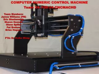
At the CNC milling machine: • Insert the flash drive into the computer • open the “Velocity 4CNC” software • select “File”, “Open NC Code” • Select your file (NCC file extension) • Open the code editor. • Insert a line of code at the start of the program before the “M3” line that reads “G00 Z.3” • Insert a line of code at the end of the program directly prior to the “M5” line that reads “G00 X0 Y0 Z.3” • Exit the code editor. • Run an emulation • Verify that the tool path is accurate • secure your material on the mill • Turn on the mill • Zero the cutter to the material • Zero the software • Cut the material.