Download
1 / 27
280 likes | 413 Views
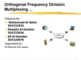
OFDM Transmission Technique Orthogonal Frequency Division Multiplexer. EE 578 Assignment # 4 Mohammad Alkhodary ID: 200806080. Concept of parallel Transmission . Concept of parallel Transmission schemes .

E N D
OFDM Transmission Technique Orthogonal Frequency Division Multiplexer EE 578 Assignment # 4 Mohammad AlkhodaryID: 200806080
Concept of parallel Transmission Concept of parallel Transmission schemes • The maximum delayed time of the delayed waveform is greater than 2 symbols time, therefore booth the spectrum and waveforms are distorted. • Implementation Difficulties have been encountered in using adaptive equalizer at High rate.
Concept of parallel Transmission Parallel transmission • the delay time of the delayed waves is suppressed to within 1 symbol time.
Concept of OFDM ISI and ICI Still problems • The spectra of an OFDM signal are not strictly band-limited, the distortion, due to multipath fading, causes each subchannelto spread the power into the adjacent channels. • To reduce the distortion, a simple solution is to increase the symbol duration or the number of carriers. However, this method may be difficult to implement in terms of carrier stability against Doppler frequency and FFT size.parallel Transmission
Concept of OFDM ISI Solution • One way to eliminate lSIis to create a cyclically ex tended guard interval, where each OFDM symbol is preceded by a periodic extension of the signal itself. • When the guard interval is longer man the channel impulse response, or the multipathdelay, the effect of lSI can be eliminated. • Usually
OFDM Receiver Received signal and Channel Equalization • characteristic of delayed wave
OFDM Transmission Scheme • The multipath fading environment in time domain is characterized by impulse responses with different delays an powers. • In frequency domain, it is characterized by attenuation or enhancement of different frequencies of the impulse responses
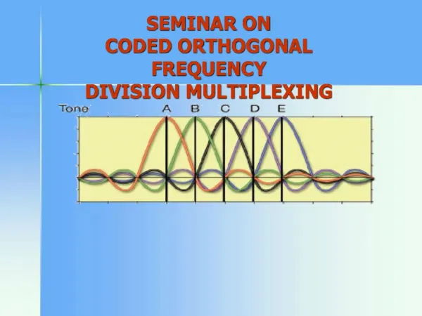
OFDM Transmission • The signal is given by: • The subcarrier is given by:
When Bs > Bc, distortion increases but the total received power variation is less. • When Bs < Bc, distortion is little but the total received power is attenuated. • We use parallel transmission to solve this problem. • The high rate is decreased as we multiplex the data while the symbol duration increases.
Guard Bands • Used to eliminate ISI that appears in the received signal. • Ttotal= Tg + Ts • Tg < Ts/4
BER & PER Performance Thank You
Pilot Symbol Aided OFDM • Compensate for the phase and amplitude fluctuation. • Pilot symbols are inserted in at the transmitter at fixed time interval. • At the receiver, we estimate the channel behavior using the pilot symbols. • Fluctuation is independent of pilot symbols.
Frame Format Configuration • Sampling rate: 20 MHz . • Modulation scheme. • FEC: R= ½, K= 7 • Frame format . • Radio channel model.
OFDM Performance OFEM BER • The BER depends on me level of the receiver's noise. In OFDM transmission, the orthogonalityis preserved, and the BER performance depends on the modulation scheme in each subchannel.