Download
1 / 28
300 likes | 427 Views
EE4271 VLSI Design. Dr. Shiyan Hu Office: EERC 518. Manufacturing Process I. Adapted and modified from Digital Integrated Circuits: A Design Perspective by Jan M. Rabaey, Anantha Chandrakasan, and Borivoje Nikolic. Silicon Wafer. Single die. Wafer. Going up to 12” (30cm).

E N D
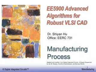
EE4271VLSI Design Dr. Shiyan Hu Office: EERC 518 ManufacturingProcess I Adapted and modified from Digital Integrated Circuits: A Design Perspective by Jan M. Rabaey, Anantha Chandrakasan, and Borivoje Nikolic.
Silicon Wafer Single die Wafer Going up to 12” (30cm) From http://www.amd.com
Dual-Well Process Wires on the top Dual-Well Trench-Isolated CMOS Process Transistors at bottom
VLSI Design and Fabrication Lithography Process Fabricated Chip Designed Chip Layout 7
Lithography System - Simple View Illumination source Mask Objective Lens Aperture Wafer 9
Photo-Lithography Process – Full View Part of layout optical mask oxidation photoresist photoresist coating removal (ashing) stepper exposure Typical operations in a single photolithographic cycle (from [Fullman]). photoresist development acid etch process spin, rinse, dry step 10
An Example: Patterning of SiO2 Chemical or plasma etch Si-substrate Hardened resist SiO 2 (a) Silicon base material Si-substrate Photoresist SiO 2 (d) After development and etching of resist, chemical or plasma etch of SiO 2 Si-substrate Hardened resist (b) After oxidation and deposition SiO of negative photoresist 2 Si-substrate UV-light Patterned (e) After etching optical mask Exposed resist SiO 2 Si-substrate Si-substrate (f) Final result after removal of resist (c) Stepper exposure
Manufacturing Process • Part of the layout is put on a mask (level), so we have many masks. • Each mask level corresponds to different actions in the fabrication process • Each mask level contains non-overlapping polygons, but polygons from different masks may overlap
An Example A set of masks
An Example - VI Insulator SiO2 for building metals in next step Active (diffusion) contact
Define active areas Etch and fill trenches Implant well regions Deposit and pattern polysilicon layer Implant source and drain regions and substrate contacts Create contact and via windows Deposit and pattern metal layers General CMOS Process
Contact and Via • Contact: • link metal with diffusion (active) • Link metal with gate poly • Via: • Link wire with wire • Overlapping two layers (diffusion, gate poly or metal) and providing a contact hole filled with metal • Substrate Contact and Well Contact: • Link substrate or well to supply voltage
p-epi (a) Base material: p+ substrate with p-epi layer (extended layer) + p Si N 3 4 SiO (b) After deposition of gate-oxide and 2 p-epi sacrificial nitride (acts as a buffer layer) + p (c) After plasma etch of insulating trenches using the inverse of the active area mask p + CMOS Process Walk-Through
SiO (field oxide) 2 (d) After trench filling, CMP planarization, and removal of sacrificial nitride n (e) After n-well implants (by adjusting well doping in order to have more donar impurities such as phosphorus) p (f) After p-well implants (by adjusting well doping in order to have more acceptor impurities such as boron) CMOS Process Walk-Through This implant will only impact the area below the gate oxide but not gate oxide itself
poly(silicon) (g) After polysilicon deposition and etch n + + p (h) After n + source/drain and p + source/drain implants. SiO 2 (i) After deposition of SiO 2 insulator and contact hole etch. CMOS Process Walk-Through
Al (j) After deposition and patterning of first Al metal layer. Al SiO 2 (k) After deposition of SiO 2 insulator, etching of via’s, deposition and patterning of second metal layer of Al. CMOS Process Walk-Through
CMOS Polysilicon Aluminum