Download
1 / 27
270 likes | 352 Views
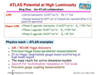
ATLAS Workshop, May 15-16, ANL. ATLAS Multi-User Potential. P.N. Ostroumov B. Mustapha, A. Perry (IIT), M. Fraser (CERN) – Beam optics and hardware design S.A. Kondrashev, C. Dickerson, R. Vondrasek – EBIS development May 15, 2014. Motivations.

E N D
ATLAS Workshop, May 15-16, ANL ATLAS Multi-User Potential P.N. Ostroumov B. Mustapha, A. Perry (IIT), M. Fraser (CERN) – Beam optics and hardware design S.A. Kondrashev, C. Dickerson, R. Vondrasek – EBIS development May 15, 2014
Motivations • The issue: In the past 2 years, the requested experimental beam time significantly exceeded the 5000-5500 hours that ATLAS can deliver yearly. With CARIBU online, the demand for beam time may double. • The solution: Develop and implement a system for the delivery of stable and radioactive beams to 2 or 3 experiments simultaneously. • The upgrade could be performed in three stages ATLAS Multi-User Potential ATLAS Workshop
Stage I of the ATLAS Multi-User Upgrade • Will allow: • The simultaneous acceleration of two beams • One stable from ATLAS-ECR and one radioactive from CARIBU-EBIS • One to the Booster energy and one to the full ATLAS energy • Will require • Replacing the ECR charge breeder with the newly developed EBIS breeder • Building an achromatic LEBT upstream of the RFQ • Building a pulsed switchyard for one beam extraction at the end of Booster • Relocating and installing an existing ECR as a second source for stable beams ATLAS Multi-User Potential ATLAS Workshop
EBIS: A Key Component of ATLAS Multi-User Upgrade • Will be installed on-line in 2015, replaces ECR charge breeder ATLAS Multi-User Potential ATLAS Workshop
EBIS Charge Breeder: Successful Off-line Commissioning • Measured Cs transmission efficiency: 55 ± 5 % ~ 13% breeding efficiency into a single charge state • Will be ready for online installation at CARIBU in 2015 – already funded • Will enhance both the intensity and purity of CARIBU beams ATLAS Multi-User Potential ATLAS Workshop
Time Structure of CARIBU-EBIS and ATLAS-ECR Beams Radioactive ions from CARIBU-EBIS • EBIS beam is ~ 10 μs to 1 ms pulse with 30 Hz repetition rate < 3 % DF • DC beam from ECR could be injected into ATLAS in the remaining 97% DF • CARIBU Beam masses range from 80 to 170 with Z ranging from 30 to 70 • The highest charge-to-mass ratio they could be ionized to is 1/4. • ATLAS accelerates any beam with a charge-to-mass ratio > 1/7 • The useful charge-to-mass ratio range for the multi-user capability is 1/7 to 1/4 • If EBIS is operated at 10 Hz, higher q/A 1/3 can be achieved t Up to 3% Duty Factor Stable ions from ATLAS-ECR t 96 % Duty Factor Combined beam structure t ATLAS Multi-User Potential ATLAS Workshop
Stage I: Modify Injection to combine two beams CARIBU • New achromatic LEBT to transport beams of slightly different q/A • Pulsed electrostatic deflector to combine stable beam from ECR and RIB from EBIS Second ECR ECR-2 EBIS EBIS replacing ECR-1 charge breeder Pulsed E-Deflector RFQ Achromatic LEBT PII ATLAS Multi-User Potential ATLAS Workshop
Stage I: More Examples of Possible Simultaneous Beams Q/A is within 1% for Each Raw ATLAS Multi-User Potential ATLAS Workshop
Stage I More Examples of Possible Simultaneous Beams (2) ATLAS Multi-User Potential ATLAS Workshop
ATLAS as a Multi-User Facility, Stage I • Area II, ~ 6 MeV/u ion beam • (9 -15) MeV/u beam to Area III or IV Pulsed switchyard ECR ATLAS Multi-User Potential ATLAS Workshop
Stage I Example: Detailed start-to-end 3D beam dynamics simulations 132Sn27+ from EBIS and 48Ca10+ from ECR 48Ca10+ at 5.9 MeV/uextracted and sent to Area II 132Sn27+ at 5.9 MeV/u injected into ATLAS 132Sn27+ at 10 MeV/u out of ATLAS to Areas III or IV ATLAS Multi-User Potential Heavy-Ion Discussion Group
Stage I: Schedule and Funding • Schedule • Could be completed in two years from now • EBIS installation will take 3 months and is scheduled for next year. It will not interrupt ATLAS operations with stable beams • Installation and commissioning of the achromatic LEBT and pulsed switchyard can take 2-3 months and can be done during ATLAS scheduled shutdown • This installation schedule is based on our experience with the recent ATLAS upgrades: LEBT modification, RFQ installation and Booster upgrade. • If the project starts in 2015, the completion is most likely in 2017 • Funding: • The EBIS installation is funded by Accelerator Improvement funds (AIP) • Relocation of the existing ECR is partially funded by ATLAS Capital Equipment funds • New funding is required for a building extension to house the second ECR- $0.6M, achromatic LEBT and switchyard - ~$1M • Total required funding is ~ $2M ATLAS Multi-User Potential ATLAS Workshop
Stage II of the ATLAS Multi-User Upgrade • Will allow: • Simultaneous acceleration of two beams (one stable and one radioactive) to the full energy of ATLAS • The acceleration of higher intensity stable beams to the full ATLAS energy Higher intensity radioactive beams from AIRIS (see C. Hoffman’s Talk) • Will require • Replacing the three old split-ring cryostats with two new QWR cryostats, one 72 MHz (intensity upgrade) and one 109 MHz (energy upgrade). • Upgrading the existing 109 MHz cryomodule with an additional cavity and replacing VCX tuners to allow 3 MV voltage operation • Modifying the 40-deg bend to be achromatic • Reconfiguring the shielding to accommodate higher intensity beams in ATLAS • Creating a pulsed switchyard upstream of Area III • Example of beams: • 132Sn from CARIBU and the EBIS breeder going to HELIOS, • 48Ca (Q=9, 10, or 11) to 64Ni region from the ECR ion source going to either the FMA or AGFA for heavy element spectroscopy ATLAS Multi-User Potential ATLAS Workshop
Stage II: Replace old split-ring resonators with new QWRs • Table of possible beam energies in the Booster and ATLAS after one and two new cryostats (no stripping required) • Upgrade existing 109 MHz cryomodule: add additional cavity, replace VCXs, average voltage per cavity is 3 MV • A new =0.077 QWR cryomodule, 7 cavities, VACC=3 MV • A new =0.15 QWR cryomodule, 8 cavities, VACC=3 MV ATLAS Multi-User Potential ATLAS Workshop
Stage II: Schedule and Funding • Schedule • Construction and off-line commissioning of two new cryomodules: 4-5 years. It will not interrupt ATLAS operation • Installation and beam commissioning of cryomodules, relocation of the existing 109 MHz cryomoduleand installation of achromatic 40-deg bend: 6 months • This installation schedule is based on our recent experience with substantial modifications of the Tandem and Booster areas • Funding • Upgrading the existing 109 MHz cryomodule, AIP funding, $1.5M. It will take place independently from the multi-user upgrade • Two new cryomodules, 40-deg bend, enhanced shielding walls: ~$(10-12)M ATLAS Multi-User Potential ATLAS Workshop
Stage III of the ATLAS Multi-User Upgrade • Will allow: • The simultaneous acceleration of three beams; two stable and one radioactive to either Booster or ATLAS energy to serve 3 different experiments simultaneously • Even higher intensity ATLAS beams, both stable from a new SC ECR and radioactive by combining multiple charge states • Intensities of stable beams will be a factor of 5-10 higher than now • Will require: • Replacing one of the existing ECR with a new high-performance SC ECR source • Developing and installing a chopper system in the LEBT to inject two stable beams with close q/A into two separate RF buckets of the RFQ • Modifying the injection for multiple-charge-state radioactive beams from EBIS • Developing and installing two RF switchyards for Areas II and III • Modifying experimental beam lines to allow the transport of multiple-charge-state and larger emittance beams • Example of Beams: • 102Ru to HELIOS and 208Pb to Gammasphere and a radioactive beam to Target Area II or III, IV. ATLAS Multi-User Potential ATLAS Workshop
Stage III: Schedule and Funding • Schedule • Longest lead time is the development of the SC ECR: 4 years. It can be started now if funding is available • All modifications of ATLAS injector, beamlines can be performed in parallel with ATLAS operations • May require one month of beam commissioning to implement new modes of ATLAS operation • Funding • $(6-8)M, the most costly item is the SC ECR ATLAS Multi-User Potential ATLAS Workshop
Past Performance Guarantees Future Success • 3 ATLAS Upgrade projects: RFQ, Cryomodule and EBIS were delivered on schedule with originally conceived parameters ATLAS Multi-User Potential ATLAS Workshop
Summary • The first stage of the Multi-User Upgrade can be implemented within 2 years at low cost • Replacement of remaining 3 split-ring cryomodules with 2 new cryomodules enables the acceleration of different q/A beams to the highest available energies including dual charge state beam from CARIBU EBIS • Once a decision is made to build 2 new cryomodules, we can proceed with the next 2 stages of the multi-user upgrade. ATLAS Multi-User Potential ATLAS Workshop
Questions? ATLAS Multi-User Potential ATLAS Workshop
Back-up Slides ATLAS Multi-User Potential ATLAS Workshop
Stage I: Add Switchyard to extract one beam after Booster • Build a chicane under the main ATLAS beam line to extract one beam to Area II • The second beam continues to ATLAS for further acceleration for Area III or IV • The chicane consists of a pulsed kicker, a septum and three regular magnets • The 40-deg bend will be modified to be achromatic for future stages of the upgrade ATLAS Multi-User Potential ATLAS Workshop
Stage I Example: 132Sn27+ from EBIS and 48Ca10+ from ECR 132Sn27+ 48Ca10+ Two separate beams at their sources Combined beams in the LEBT Two beams injected into the RFQ ATLAS Multi-User Potential Heavy-Ion Discussion Group
Stage I Example: 132Sn27+ from EBIS and 48Ca10+ from ECR (2) 132Sn27+ 48Ca10+ Two beams out of RFQ into PII Two beams out of PII into Booster Two beams out of Booster @ 5.9 MeV/u ATLAS Multi-User Potential Heavy-Ion Discussion Group
Kicker Magnet • Pulsed magnet • Could be iron or ferrite magnet • Ferrite magnets • Rise- and fall-time can be very short – nsec • Operate at high frequencies, MHz • High resistivity, low eddy current • Saturation field is up to 0.6T • Low inductance – single-turn coil • Pulse Forming Network (PFN) as a power supply ATLAS Multi-User Potential ATLAS Workshop
Septum Magnet, DC Magnet • Required current ~kAmps • Very high power is needed – up to 100 kW Beamline ATLAS Multi-User Potential ATLAS Workshop
Stage II of Multi-User Upgrade • Remove all split-ring cryomodules New cryomodule =0.15, 8 cavities Pulsed switchyards New cryomodule =0.077 ATLAS Multi-User Potential ATLAS Workshop