Download
1 / 49
880 likes | 1.6k Views
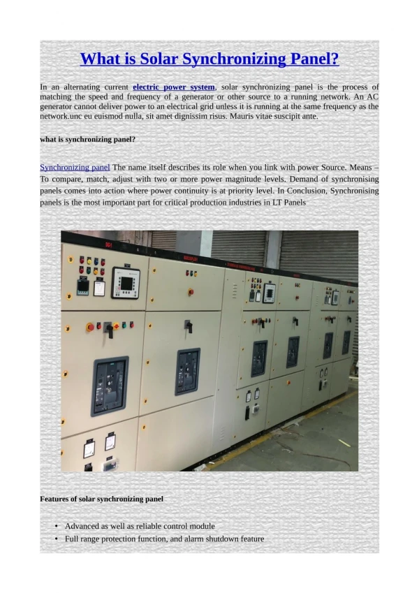
Synchronizing. WECC System Operator Training. Synchronizing. Introduction Synchronism is the condition that exists when two parts of a power system are electrically tied together, in phase with each other, and operating at the same frequency.

E N D
Synchronizing WECC System Operator Training
Synchronizing • Introduction • Synchronism is the condition that exists when two parts of a power system are electrically tied together, in phase with each other, and operating at the same frequency. • Synchronizing is the process of putting two separate energized parts of a power system into synchronism by connecting them together, usually by closing a circuit breaker. • Synchronizing is sometimes called paralleling. 3
Synchronizing • Improper synchronizing or loop closing can cause serious disturbances or power outages due to equipment damage and instability. • While you may or may not be doing actual synchronizing, it is important for you to be familiar with the process. • Even if you don't normally operate the synchronizing controls, you will often order and/or direct their operation. • All synchronizing should be done at a system operator's direction. 3
Basic Considerations • Four parameters must match within reasonable limits before connecting • Phase rotation • Frequency • Voltage • Phase angle 4
Basic Considerations • Phase rotation • A-phase connected to A-phase, etc. • Must be exactly correct - otherwise, have a 120o phase angle upon connecting • Usually addressed during construction and dispatchers don’t have to worry about it 4
Basic Considerations • Frequency on both sides of open point • Most critical consideration after phase rotation • Must match very closely • Connecting at different frequencies shocks the system and equipment 4
Basic Considerations • Voltage on both sides of the open point • Must match within acceptable limits - up to 10% difference may be acceptable • Any voltage magnitude difference will result in reactive power flow as soon as the breaker is closed. 4
Basic Considerations • Voltage phase angle difference • Should be reduced as much as possible before closing • Phase angle difference causes power to flow from leading to lagging side • The greater the phase angle, the greater the shock to the system 5
Summary • Bad things can happen when these parameters are mismatched. • Energy and VAR transfers take place and there is a possibility of equipment damage or system instability. • An important synchronizing objective is to match these parameters so there will be little or no energy transfer. 5
Synchronizing Equipment • The Synchroscope 5
Synchronizing Equipment Synchronizing – Dark Lamp Method http://www.jcmiras.net/jcm2/p17.htm 6
Now for a most important point: the synchroscope pointer is hooked to theincoming side and shows what incoming is doing with respect to running. Let’s look at three examples.
Now for a most important point: the synchroscope pointer is hooked to theincoming side and shows what incoming is doing with respect to running. Let’s look at three examples. 1. The pointer is turning rapidly in the slow direction. • Since the pointer tells us what incoming is doing relative to running, turning in the slow direction means that the incoming side frequency is slower than the running frequency. If we were synchronizing a generator to the system, we would need to speed it up to match system frequency. • Since the pointer is spinning rapidly, it tells us there is a large frequency Difference.
Now for a most important point: the synchroscope pointer is hooked to theincoming side and shows what incoming is doing with respect to running. Let’s look at three examples. 2. The pointer is turning slowly in the fast direction. • This tells us that the incoming frequency is faster than the running frequency. • The frequency difference is not very great.
Now for a most important point: the synchroscope pointer is hooked to theincoming side and shows what incoming is doing with respect to running. Let’s look at three examples… 3. The pointer is stopped at 45 degrees in the fast direction. • A stationary pointer indicates that the incoming frequency and the running frequency are the same. • There is a 45 degree phase angle difference between the incoming and running voltages. • Since the pointer is in the fast direction, it indicates that the incoming side voltage phase angle is leading the running side voltage phase angle.
Now for a most important point: the synchroscope pointer is hooked to theincoming side and shows what incoming is doing with respect to running. Summary of three examples 1. The pointer is turning rapidly in the slow direction. • Since the pointer tells us what incoming is doing relative to running, turning in the slow direction means that the incoming side frequency is slower than the running frequency. If we were synchronizing a generator to the system, we would need to speed it up to match system frequency. • Since the pointer is spinning rapidly, it tells us there is a large frequency Difference. 2. The pointer is turning slowly in the fast direction. • This tells us that the incoming frequency is faster than the running frequency. • The frequency difference is not very great. 3. The pointer is stopped at 45 degrees in the fast direction. • A stationary pointer indicates that the incoming frequency and the running frequency are the same. • There is a 45 degree phase angle difference between the incoming and running voltages. • Since the pointer is in the fast direction, it indicates that the incoming side voltage phase angle is leading the running side voltage phase angle.
Paralleling Two Islands • Separation of the WECC Interconnection into more than one energized island thankfully doesn't happen very often. • When it does, however, the islands have to be put back together by paralleling or synchronizing (the two terms mean the same thing). • Paralleling two islands requires careful matching of the three synchronizing parameters under system operator control. 10
Paralleling Two Islands • Matching frequency comes first. • Next is matching voltage. • Lastly, we must match voltage phase angles. 10
Closing a Loop • Closing a loop, while technically not synchronizing because both sides of the loop are electrically tied together at some other point, is discussed with synchronizing because the same parameters must be matched and the same equipment is used. • Open loop conditions may occur during normal switching. • They may also result from line trips due to faults or instability. • Automatic reclosing after a line trip is an example of closing a loop. 11
Closing a Loop • It is easy to match the first two parameters when closing a loop. • Since it is a loop, it is one system and not two. Therefore, the frequency is the same on both sides. • This shows up as a stationary synchroscope pointer. • Voltage can be matched using voltage control devices in the same way as in paralleling two islands. 11
Closing a Loop • The major difficulty in closing a loop is matching the voltage phase angles, especially on a long loop. • Since the phase angle difference represents the "desire" of power to flow when the open point is closed, we have to change the "desire" in order to change the phase angle. 11
Zeroing Schedules • WECC Operating Procedures Section 5.A.7 states: • Zeroing schedules. Energy schedules on a transmission path shall be promptly reduces to zero following an outage of the path unless a back-up path has been pre-arranged. • If a system disturbance results in system islanding, all energy schedules across open paths between islands shall be immediately reduced to zero unless doing so would prolong frequency recovery. 11
Additional Ideas on Synchronizing • Degrees vs. Minutes • 6 degrees equals 1 minute • Breaker closing speed • Synchroscope operation • Automatic Synchronizing • Synchrocheck or Synchroverifier 13/14
Additional Guidelines • When synchronizing two islanded systems, first ensure that at a minimum: • The synch-panel is monitoring the correct CB to energize the intended facility • The synchroscope is operating as evidenced by a rotating needle • If the synchroscope is not rotating, do not assume the frequencies are matched, the scope may be broken or the frequency difference may be too large for the scope needle to keep up with the magnetic field rotation 14
Additional Guidelines • All customer load pick-up, generator ramping, and AGC actions are suspended for the duration of the synchronizing process • That no generator governor is set in a 0% droop mode Once the conditions listed above have been satisfied, a typical synchronizing process usually contains the following steps: • The frequency of each system should be adjusted to a common value • Normally as close to 60 HZ as possible 14
Additional Guidelines • The voltage on each side of the open CB should be adjusted to a common value • The greater the magnitude difference, the greater the initial Mvar flow • The synchroscope needle must be rotating to prove the scope is working • The speed of one or both of the islands is adjusted so that the synchroscope needle is rotating very slowly • Typically, slowing the “running” side system slows the clockwise rotation of the synchroscope and speeding up the running system slows counter-clockwise rotation • A slight initial speed adjustment is often used to verify the appropriate speed adjustment needed to slow the scope down 14
Additional Guidelines • Once all the previous steps have been taken and verified, the CB should be closed at the moment when the scope needle is approaching the 12 o’clock position • The 12 o’clock position is a 0° power angle 15
SYNCHRONIZING REVIEW WECC System Operator Training
REVIEW • TRUE OR FALSE= A synchroscope is supplied by and makes comparison of single phase potentials on each side of the open point • True
REVIEW • Name three (3) locations that should have synchronizing capability: 1. Intertie Lines 2. A thermal generating station 3. A hydro plant in a remote area
REVIEW • TRUE OR FALSE= If the potential transformer fuses were blown on the bus potentials, to synchronize two systems you would need to find another synchronizing point on the system. • True
REVIEW • There are 360 electrical degrees represented by one revolution of a synchroscope. Each "minute" on a synchroscope represents how many electrical degrees? • 6
REVIEW • TRUE OR FALSE= Regarding standard synchroscope connections, the expected source of "incoming" synchroscope potential at a transmission substation is line potential. • True
REVIEW • Name three (3) synchronizing "out-of-phase" close to a major transformer bank and source of generation may result in: • Physical damage to the bank and/or generating units • System inertia swing and possible automatic relay action • Power exchange across the point of synchronizing
REVIEW • TRUE OR FALSE= When an out-of-step relay senses a swing into the relay's range, it can tell the difference between a swing and a fault by the rate of the change of the apparent impedance (or reactance or admittance). • TRUE
REVIEW • TRUE OR FALSE= If a synchroscope is rotating in the fast direction, this means the “incoming” source is fast • True
REVIEW • TRUE OR FALSE= A relay most commonly used to automatically synchronize generating units to the system, considering speed difference, voltage magnitude, rate-of-change and CB closure time is an intended function of a synchronism check relay. • True
REVIEW • TRUE OR FALSE= Following a disturbance which islanded your utility from the WECC network your system frequency indicated 59.92 Hz and the WECC network frequency indicated 60.02 Hz. If you were doing the synchronizing at your station, the direction the synchroscope needle would be turning is in the fast direction. • True
What we covered this week…… • Primary Topics include: • Protective Relaying • Introduction to Protective Relaying • Purpose & Function of Protective Relays • Characteristics of Relay Devices • IEEE Numbering Convention for Relay Devices • Power System Faults • Instrument Transformers • Relay Construction & Operation • Types of Relays • Transmission Line Protection Systems • Substation Equipment Protection Systems • Generator Protection Systems • Remedial Action Schemes (RAS) • WECC RAS #1 Scheme Review & Test #1
What we covered this week….. • Primary Topics include: • Additional Equipment & Topics • Solar Magnetic Disturbances (SMD’s) • Sunspots • Factors that influence SMD’s • Impact of SMD’s on the Transmission System • Controlling the Impact of SMD’s on the Transmission System • Example of SMD events • Role of the System Operator • High Voltage DC • Types of HVDC Systems • Components of HVDC Systems • Operation of HVDC Systems • Introduction to Phase Shifting Transformers • NERC Standards addressing Transmission Operations & Protective Relaying Review
What we covered this week….. • Primary Topics include: • Synchronizing • The four requirements • The synchroscope • Paralleling a generator • Joining two islands • Closing a loop Review & Test #2
What we covered Please turn in= Class evaluations Plastic badge holders