Download
1 / 41
410 likes | 516 Views
Richieste per l’esperimento MEG (in costruzione). Timing counter: illustrazione dello stato attuale: richieste sblocchi s.j. per Genova e di sblocco + ulteriore assegnazione per Pavia

E N D
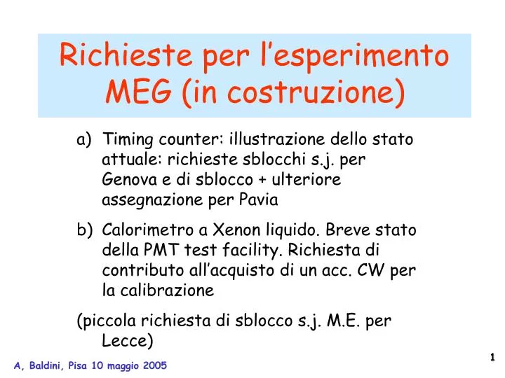
Richieste per l’esperimento MEG (in costruzione) • Timing counter: illustrazione dello stato attuale: richieste sblocchi s.j. per Genova e di sblocco + ulteriore assegnazione per Pavia • Calorimetro a Xenon liquido. Breve stato della PMT test facility. Richiesta di contributo all’acquisto di un acc. CW per la calibrazione • (piccola richiesta di sblocco s.j. M.E. per Lecce)
a) TC: TC Final Design • A PLASTIC (BLACK PLEXIGLASS) SUPPORT STRUCTURE ARRANGES THE SCINTILLATOR BARS AS REQUESTED • THE BARS ARE GLUED ONTO THE SUPPORT • “LIGHT” INTERFACE ELEMENTS ARE GLUED ONTO THE BARS AND SUPPORT THE FIBRES • FIBRES ARE GLUED AS WELL • TEMPORARY ALUMINIUM BEAMS ARE USED TO HANDLE THE DETECTOR DURING INSTALLATION • PTFE SLIDERS WILL ENSURE A SMOOTH MOTION ALONG THE RAILS
TC final design (PMTs interface to scintillators) • PMTs ARE ATTACHED, BY MEANS OF THE INTERFACE SOCKET, TO THESCINTILLATOR BARS • GIVEN THE MASS, AN ELASTIC AND REMOVABLE SILICONE GLUE IS APPROPRIATE • THE HOLLOW INTERFACE ELEMENT IS A “CUSTOMDESIGNED” PROFILE THAT ADDS A MINIMUM AMOUNT OF MATERIAL BETWEEN THE FIBRES AND THE BARS • SLOT FOR CABLES and OPTICAL FIBERS HAVE BEEN FORESEEN TO ALLOW THE CABLES FROM THE INNER PMT TO EXIT
Under construction BC 404 scintillator bars PMT sockets Scint. Fiber adapter To be define soon Definition of the supporting structure and construction (july) Insert APD read-out system in the final design (july) APD amplifier PCB and production (end of sept.) Validation test at BTF of 10 elements of curved detectors-june (we are undertaking a preliminary test with cosmics) Final construction of whole TC (sept-nov). Estimate delivery of the timing counter end of november Test @ BTF: december Under study (advance status) TC bag TC curved detector pattern generator TC linear detector DRS matching electronics Construction status
Kapton Flex. APD Black Coating Electronics boards -10 channels Scint. Fibers Transition board Copper Cold Finger(~20°) Peltier Cell Heat Exchanger APD intercalati con passo di 5mm Vista lato frontale APD, sezione per la lettura di 10 fibre scintillanti Vista sezione trasversale con, fibre, elettronica, cooling.
TC bag inside cobra prototype design under study. Plastics considered: EVOH, SARAN, FEP, Nylon 6, TEP Polyamide
Copper block APD Splitters Pulsed Laser Peltier Cell 1/1000 attenuator Integrating Calibrated Photometer Fast Photodiode Photomultiplier TC curved (trigger & pattern):APD test system
Richieste • Ge: sblocco di 2 K€ (inv.) + 32 K€ (app.) + 15 K€ (consumo) per elettronica e meccanica sistema APD • Pv: • 21 K€ (app.) per sistema di test PMT contatore long. • 20 K€ (app.) per realizzazione sistema di misura a doppisa soglia di discriminazione (utilizzabili 20K€ s.j. per RGA) • sblocco 10 K€ M.E. S.j. • Le: • Sblocco 10 K€ M.E: s.j.
b) LXe calorimeter: Pisa PMT test facility • Solution to the Zener noise problem OK • First 30 PMTs received at pisa on may 6th • PMT testing (3-4/day)
Despite the overall determination within 5% there are systematic dependences Amplitude dependence Purity dependence can be explained with different distance from source Purity dependence gain corrected
Metodi di calibrazione e monitor per il calorimetro di MEG e per tutto l’esperimento Nota interna MEG (MEG-TN027) per la CSN1
Il controllo del calorimetro e.m. di MEG a rate di decadimento elevati e variabili BR eg~10-13 Beam Intensity~5 107 /s richiede • frequent checks of calorimeter energy scale, linearity and stability • checks of LXe optical properties • energy resolution and spacial resolution • shower properties • at the right energy ( 53 MeV), but also at other energies..... no single calibration method has all the required characteristics use complementary (and redundant) methods, make the best use of their intrinsic properties emphasize the reliability of our experiment !
1) Am SOURCES ON WIRE AND WALLS Sources in production. Soon available for all LXe devices. • Potentialities : • PMT quantum efficiencies • Xenon optical properties • low-energy position and energy • calibration • use in Xe gas and liquid • stability checks ? • a unique method for cryogenic liquid • detectors !! Wire presently mounted in “Large Prototype” • Open problems: • will the method be usable under full intensity beam conditions ? • To be verified by test !
reconstruction of the 8 -source positions in gaseous Xe. Recent measurement with the large-prototype. (Po-source produced in Genoa)
RINGS IN LIQUID XENON -range (2m) and wire shadow (100m) reflection on Al the ring radius has some dependence on the Rayleigh scattering length in LXe
Determination of the relative QE for 4 different PMTs of the large-prototype by the use of 4 dot-wire-sources in Xe gas the relative QEs are given by the slope of the linear fits.
neutron generator 20 cm 3 cm 2)THERMAL NEUTRON CAPTURE ON NICKEL D + 2H 3He + n Q = 3.27 MeV D + 3H 4He + n Q = 17.59 MeV • Potentialities : • switchable on-off • frequent (s, m,...) stability checks • system out of the calorimeter • Ni and Xe, prompt and delayed signals • probably: visible signal at full beam intensity • time reference 9 MeV Nickelγ-line • Open problems: • monitoring from calorimeter back • only at one location ? • some dispersed neutrons and radioactivity • test of the method at high beam intensity • useful test with the “large prototype” • (already foreseen....., with Am/Be source) NaI 20 x 20 x 36 cm3 Tg-on e5 beam on Tg-off • Intensities from 106 n/s to 108 n/s • Typical pulse rate and pulse width 10 Hz and 1 μs • Time separation of direct from delayed reactions • Single pulse mode Polyethylene 0.25 cm Nickel plate
large-prototype NaI /E=2.5% in the large-prototype the line is worse..... the measurement must be repeated, protecting LXe from thermal neutrons by a Boron-foil 9/(generated neutron)2x10⁻³
How often can it be performed? 3)p0calibration… Anti Counter Support structure: straightly up and down Tilt mechanism at every height for NaI front to face target direction. tilt • Proton beam: 1.8mA • 0 Rate: 106p0/sec • Collimate: 2PMTs x 2PMTs ~ 150cm2 • (1 position) • 1g/sec • # of PMTs on incident face: 216 PMTs (54 positions) • required: 10,000 evts/position • takes 10,000 x 54=540,000 s ~ 6 d • + time for movements !! g Target up p0 down g target
an interesting possibility to speed-up the calibration • abandon collimators and NaI detector in coincidence • illuminate the whole calorimeter at the same time with -1 • convert the -2 in a 0.1 X0 converter close to the H2 target • detect conversion and measure conversion point with a Si-detector • measure e+ branch of the pair in the chambers • use part of the information for selecting -2 by trigger angle between ’s defined by impact points on LXe-Cal and Si-detector (angles 1800 useful for calibrating at different energies) loss at conversion but huge increase in solid angle MC METHOD SIMULATION RESULTS A FULL TEST OF THE WIRE CHAMBERS CAN ALSO BE PERFORMED !
Un evento Hydrogen target + Tungsten converter Electron Positron Photon
Rough estimate of the time needed for the LXe calibration • <e> (20 30)/105/10 = (20 30) x 10-6 • R = Rp0 x <e> = (Rp0/106)x 106 x (20 30) x 10-6 = (20 30) x (Rp0/106) Hz • Events/day 8.64 x 10⁴ R 2 x 10⁶ x (Rp0/106) • Assuming 50 locations to be calibrated (216 PMTs in groups of 4): Events/day/location 4 x 10⁴ x (Rp0/106) largely sufficient.... Solid angle factor
WIRE CHAMBERS TEST (at full COBRA field) by - p 0 n and -2 conversion into an e+ e– pair and also by - p n and conversion into an e+ e– pair but also the Cockroft-Walton allows a calibration of the LXe Cal and of the wire-chambers • CW use is much simpler than calibration ! • LXe Cal illuminated by 17.6 MeV ’s at high rate • Use of -converter for testing the wire-chambers • but maximum COBRA field for LXe Cal test • half COBRA field for wire-chamber test
4) 500 KV PROTON ACCELERATOR AND LITIUM TARGET FOR A 17.6 MEV GAMMA LINE 37Li (p,)48Be [P.R. 73, 666 (1948), N.P. 21 1 (1960), Zeitschrift f. Physik A351 229 (1995)] • Potentialities : • a unique nuclear reaction with a high energy -line • obtainable : at resonance (E p =440 keV 14 keV) • 106 /s (isotropic) for Ip 50 A • from LiF target at COBRA center; ’s on the whole cal. entrance face • energy and position calibration; shower properties; all over LXe cal. • monitoring at the back of the calorimeter • possibly front: rather frequent use , back: frequent use • Open problems: • compatibility with normal beam and target ? • COBRA field, accelerator and focusing element positions • project for easiness of target-tube mounting • p-beam divergence and protons on target; p29 MeV/c • post-acceleration to scan the resonance
37Li (p,)48Be resonant at Ep= 440 keV =14 keV peak = 5 mb E0 = 17.6 MeV E1 = 14.6 6.1 Bpeak 0/(0+ 1)= 0.720.07 NaI 12”x12” spectrum Crystal Ball Data 0 1
another interesting possibility...... Cecil et al. NP A539 75 (1992) 10x10 cm NaI crystal 511B (p,)612C resonant at Ep= 163 keV = 7 keV E0 = 16.1 MeV peak = 5.5 b E1 = 11.7 + 4.4 peak = 152 b • 7500/s (isotropic) • 20.0001/s for Ip 50 A lower proton energy ! lower rate at 50 A !!
the High Voltage Engineering 0.5 MeV Cockroft & Walton model: “coaxial SINGLETRON” with H+plasma source
Cal. calibration from the target position,monitoring at the cal. back rails cockroft focusing elements (magnetic or electrostatic ?) at the cal. back the proton motion in the COBRA field must be studied
Plane Z = 0 cm proton MC trajectoriesEp 440 keV 28 MeV/c!! Y(cm) ρ ~0.8cm Θ ~ 0.5 giroradius < 1 cm (Θ ~ 8 giroradius < 12 cm) X(cm) the protons are notreflected back by the varying magnetic field Z(cm)
The old Van der Graaf of the previous e g experiment ....... generates an e+ e– pair, at 17.6 MeV, seen in the GLAST calorimeter
RADIO FREQUENCY QUADRUPOLE ACCELERATOR • practically monoenergetic • pulsed operation; frequency 100 Hz 100 ms pulses • average current 50 mA , pulsed current 5 mA • beam energy bin approx. 50 keV • small vessel • beam optical properties ? 1mm ; 20 mR • RF radiation ? No • proton source ? Plasma • cost ? !!!!! • special design....time to produce ? One year • not an out-of-the-shelf machine • Companies: AccSys, Neue Technologien GMBH
Conclusioni e richieste sulle calibrazioni • Monitorarefrequentementela risoluzione in energia di fotoni (E >15 MeV) entranti dalla faccia frontale e’ l’unico mododirettoper tenere sotto controllo il fondoaccidentale • Il metodo del 0non puo’ essere usato se nonuna volta ogni qualche (6 –12 ?) meseperche’ si prevede una durata di questo calibrazione per circadue settimane. • Con il CW si puo’ pensare ad una calibrazione (forse) giornaliera. • Il CW consentirebbe un ulteriore numero di possibili calibrazioni e il miglior utilizzo del tempo fascio • Costo: 500 K€. Proposta di sharing al 50% con un gruppo di UCI (Bill Molzon)
Item Cost (K€) LXe cryostat 400 PMTs test and purchase 600 Timing counter 700 Splitters 100 Trigger 400 Total 2200 Dal MoU di MEG Appendix 1. INFN contribution to the different subdetectors
Stime di costo aggiornate Previsioni AssegnazioniRisparmi • LXenon • PMT 500 K€ -100K€ • Criostato200 K€ (criostato) • 160 K€ (supporto + finestre)-40K€ • Trigger • Prototipi 40 K€ • Sistema completo 145+115 K€ • -100 K€ • Timing counter • APD + fibre (interno) (160) 130K€ -30 K€ • PMT (100: esterno) (315) 135 K€ • -180 K€ • Scintillatore 50 K€ • Calibrazione 100 K€ • Meccanica60 K€ • Risparmio totale -225K€ • (rispetto ai 700 K€) • Splitters • Sistema completo 115 K€ • +15 K€ • Non previsti: • Software 22 K€ • Calibrazioni 50 K€ • PMT 170 K€ 242 K€ TOTALE MoU 2200 K€ Assegnato1602 K€ Previsto finale 1992 K€ Risparmio 208 K€
Budget (K€) +700 (400 PMT) +500 (aumento costo Xenon: non previsto)