Download
1 / 38
380 likes | 501 Views
Rail_test_system.pptx Aug 12, 2010 version. TPC – Time Projection Chamber (main detector in STAR) HFT – Heavy Flavor Tracker SSD – Silicon Strip Detector IST – Inner Silicon Tracker PXL – Pixel Detector (PIXEL). rail test system. rail_test_system.SLDASM

E N D
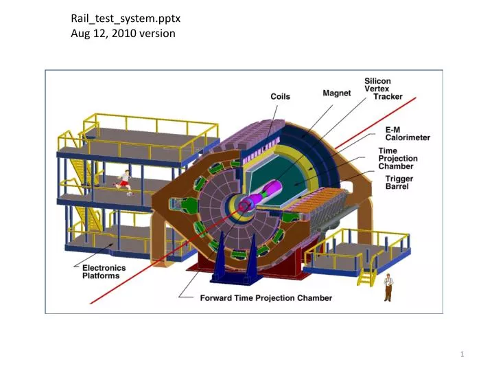
Rail_test_system.pptx Aug 12, 2010 version
TPC – Time Projection Chamber (main detector in STAR) HFT – Heavy Flavor Tracker • SSD – Silicon Strip Detector • IST – Inner Silicon Tracker • PXL – Pixel Detector (PIXEL)
rail test system rail_test_system.SLDASM http://www-rnc.lbl.gov/~wieman/container_UTA_7_8_10.zip 8/12/2010 this document: http://www-rnc.lbl.gov/~wieman/Rail_test_system.pptx
parts list for subassembly: PIT_rail_20mm_assembly.SLDASM (on test)
parts list for subassembly: PIT_rail_20mm_assembly.SLDASM (on test)
details for rail_test_system.SLDASM pages 8-14 tolerances: ±0.25 mm unless specified
LBNL water jet from 2 in MIC6 leave ¼ in on outer edges and round hole to be machined off cut lightning holes on model line east side west side east side west side after water jetting these parts will be sent to UTA for final machining PIT_end_fixture.SLDPRT (PIT east end) PIT_end_fixture.SLDPRT (PIT west end)
hole position tolerance: ±0.05 mm hole diameter tolerance: -0.013 mm press fit for bullet/diamond pin liners surface location tolerance: ±.050 mm sets SSD location and probably sets glue bond thickness hole position tolerance: ±.025 mm hole diameter tolerance: +0.013 mm for slip fit on ¼ in pin 1 of 6 location tolerance: 0.050 mm sets SSD location width tolerance: +.025 mm - .00 mm slip fit 1/8 in pin tooling ball location tolerance on front and back side: ±0.025 mm diameter tolerance: +.013 mm slip fit for Brunson adapter hole position tolerance: .05 mm hole diameter tolerance: 0.05 mm sideways hole position tolerance: ±.05 mm press fit for 1/8 in dowel pin. hole diameter tolerance: -0.013 mm ref surfaces PIT_end_fixture.SLDPRT (PIT west end) tolerances on (PIT east end) configuration the same where applicable
water jet at LBNL machining at UTA tolerances for both configurations the same as PIT_end_fixture.SLDPRT where applicable , see previous page LBNL water jet from 2 in MIC6 leave ¼ in on edges and round hole to be machined away cut lightning holes on model line ref surfaces PST_end_fixture.SLDPRT (east) west configuration similar, but fewer holes these parts are in PST_trans_v2.SLDASM which is now included in http://www-rnc.lbl.gov/~wieman/container_UTA_7_8_10.zip
both diameter tolerances: -0.013mm for slip fits IDS_flange_alignment_pin.SLDPRT
plane and parallel to ±0.05 mm length tolerance: ±0.05 mm water jet OK for lightning holes and all non specified edges water jet and machine at LBNL sideways position tolerance ±0.05 mm slip fit for 1/8 dowel pin width tolerance: +0.013 mm PIT_base_fixture.SLDPRT (PIT, PIT mid, PST) tolerances the same for all three configurations
±0.05 mm tolerances are to preserve glue bond thicknesses this and other 2 similar planes tolerances to chord and axis of ref cylinder: ±0.05 mm this plane perpendicular to a ref cylinder axis • line between • holes centered on • ref cylinder axis • to ±0.05 mm • separation tolerance • ±0.05 mm or match drilled • with butch_plate_single.SLDPRT • diameter tolerance: • +0.000 mm • 0.013 mm • for bullet insert press fit these and other similar holes diameter tolerance: -0.013 mm for press fit with tooling balls, glue in OK if ends up sloppy grand_master.SLDPRT
separation tolerance: ±.25 mm or match drill with grand_master_support_plate.SLDPRT diameter tolerance: ±0.125 mm for slip fit grand_master.SLDPRT
surfaces parallel to 0.05 mm hole position tolerance with respect to each other: ±0.05 mm can be match drilled to appropriate parts diameter tolerance: +.000 - .013 mm for press fit with bullet liners butch_plate_single.SLDPRT
position tolerance: ±.25 mm or match drill with grand_master.SLDPRT diameter tolerance: +0 -.013 mm for press fit with 1/8 inch dowel pin per McMaster Carr recommendation for their pin mill top face only from ½” stock slightly less than 1/2” thick plate no problem grand_master_support_plate.SLDPRT
details for sub assembly PIT_rail_20mm_assembly.SLDASM (on test) pages 21-36 tolerances: ±0.25 mm unless specified
tolerance OD +0-50m ID +50-0m
8-32 x 1 in aluminum cap screws vender: Fastner-express.com PIT_rail_arm_anchor_post_v2.SLDPRT PIT_rail_hanger_ext_v3.SLDPRT rail_mount_dowel_pin.SLDPRT (long) PIT_rail_arm_20mm_v2.SLDPRT cylinder_nut.SLDPRT PIT_rail_coupler_20mm_v2.SLDPRT PIT_rail_mount_20mm_v2.SLDASM ( tester normal)
fillet not important, remove sharp edges diam +.05mm - 0 #8-32 tap all small holes
diam +0mm – 0.013mm press fit with 1/8 in dowel pin diam +0-0.05 mm #8-32 tap one hole
diameter tolerance +.025-0 mm slip fit 1/8 in pin #8-32 tap 4 holes surface to cyl. surface tolerance .05 mm (controls glue bond thickness) PIT_rail_arm_20mm_v2.SLDPRT
diameter tolerance: +0-.2 mm affects rail position diameter tolerance: ±.05mm affects glue bond
thickness tolerance ± 0.13 mm for the 3 pieces
thickness tolerance ± 0.13 mm for the 3 pieces
detail from PIT_rail_20mm_single_v2.SLDASM each guide rail has one end fixed and one end sliding lengthwise
tolerance of relative position of inner holes to each other ± .025 mm (controls glue bond thickness, and must match bullet pins on other parts) inner hole diameter tolerance +0-.013 mm (press fit for bullet nose liners) make from .5” x 2” bar back side and long edges not machined, will change model to be 2 in wide
tolerance 4 outer edges ± 0.025 mm ( controls glue bond thickness and limits slider binding) tolerance inner hole position ± 0.025 mm tolerance inner hole diameter +0-.013mm (press fit nose bushings)
MC master-Carr part number 98541A139 with one ear ground off and hot glued to prevent rotation. Two retainers on each bearing liner tolerances on this part, see next page
tolerance on 4 outer edges and centers of 4 open circles ± .050 mm ( controls rail positions, must avoid slider binding) diameter tolerance of 4 open circles +0.025 mm-0 (fit bearing liners without forcing)
These 6 holes will have balls glued in. The holes are slightly oversize for a glue bond and a vent hole has been added so that the balls will not piston out due to a trapped air bubbles. These devices are designed for reproducibility of placement. Precision is not so important as long as the location of the three parts in the grandmaster_kin_assembly.SLDASM are not interchanged. These 3 parts and their positions will be labled. All fillets and chamfers shown in the model can be eliminated, deburring is sufficient Fillet from endmill radius OK kin_cross_support.SLDPRT
References: MC http://www.mcmaster.com/ FE http://www.fastener-express.com/ PB http://www.pacific-bearing.com/ CL http://www.carrlane.com/