Download
1 / 46
480 likes | 716 Views
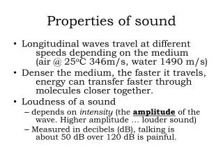
Infrasound Properties of Sound Below 20 Hz and Ways to Measure It. Jerry Brown Essex Systems Oct. 2004. A Roadmap. My client has asked that I not discuss why we were interested in infrasound. So, I will confine my discussion to

E N D
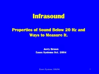
InfrasoundProperties of Sound Below 20 Hz and Ways to Measure It. Jerry BrownEssex Systems Oct. 2004 Essex Systems 10/6/04
A Roadmap • My client has asked that I not discuss why we were interested in infrasound. • So, I will confine my discussion to • The general characteristics of infrasound with particular emphasis on how it differs from higher frequencies. • How the environment interacts differently with it. • The design of an unusual infrasound microphone based on measuring particle motion with a micromachined sensor. • First, we need to review a few basic principles. Essex Systems 10/6/04
Audible Sound Essex Systems 10/6/04
The Audible Frequency Range From http://home.tir.com/~ms/concepts/concepts.html Infrasound is everything below 20 Hz, the lower limit of human hearing. Wavelength at 20 Hz is 16.6 meters (54 feet). Essex Systems 10/6/04
Another Way to Look at It From http://home.tir.com/~ms/concepts/concepts.html The “Music” portion of this graph must refer only to adult varieties or it would extend higher and further left. Essex Systems 10/6/04
The Decibel Essex Systems 10/6/04
dB Levels of Familiar Sounds COMMON SOUNDSNOISE LEVELS (dB) EFFECT Jet engine (near) 140 Jet takeoff (100-200 ft.) 130 Threshold of pain Thunderclap (near) 120 Threshold of sensation Power saw (regular > 1 Min) 110 Permanent hearing loss Motorcycle 90 Very annoying Many industrial workplaces 85 Hearing damage begins (8 Hrs) Average city traffic noise 80 Annoying. Vacuum cleaner 70 Intrusive. Normal Conversation 60 Quiet Air conditioner 50 Comfortable Whisper 30 Very quiet Normal breathing 10 Just audible 0 Threshold of hearing Essex Systems 10/6/04
Plane Waves Essex Systems 10/6/04
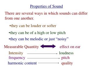
Particle Motion in a Sound WaveThe graph is animated. Click on it. • The properties which are sensed by microphones are: • Particle velocity, u, or Pressure variation, p • Important parameters are phase velocity, wavelength and frequency. Essex Systems 10/6/04
Particle velocity is quite small compared to phase velocity (which is 331 m/s at STP). For 1000 Hz at 90 dB (a very loud sound) Peak particle velocity = 1.5 mm/sec Peak pressure = 0.63 Pa or 6.2 x 10⁻⁶ atm. Peak displacement = 0.23 micron Wavelength = 0.331 meter. Typical Values at 1000 Hz & 90 dB(Plane Wave) Essex Systems 10/6/04
At 20 Hz and 90 dB (16 meters from the source). Peak particle velocity = Same (1.5 mm/sec) Peak pressure = Same (0.63 Pa) Peak displacement = 12 micron Wavelength = 16.6 m Not audible below 70 dB Values at 20 Hz & 90 dB(Plane Wave) Essex Systems 10/6/04
Values at 1 Hz & 90 dB(Plane Wave) • Finally, at 1 Hz and 90 dB (assuming that you are at least 300 meters from the source). • Peak particle velocity = Same (1.5 mm/sec) • Peak pressure = Same (0.63 Pa) • Peak displacement = 0.2 mm • Wavelength = 331 meter Essex Systems 10/6/04
Problems With Standard Microphones and Amplifiers • Microphone preamps and amps and are usually ac coupled and roll off below 20 Hz. It can be difficult to find all the coupling caps and get rid of them. • Condenser microphones have a vent hole to equalize atmospheric pressure changes. This usually acts like a high-pass filter that cuts off below 20 Hz. Essex Systems 10/6/04
The Pressure Microphone Capillary vent usually limits low frequency response. Essex Systems 10/6/04
Alternative to the Pressure Microphone • There are a few laboratory-type condenser microphones that will go down as far as 2 Hz. • With infrasound, the wavelengths are so long that observations are almost always within a wavelength of the source. This is known as the near field. • And pressure may not be the best variable to measure in the near field. Essex Systems 10/6/04
The Near Field • The near field is used in connection with sources that produce diverging spherical waves. Most real-world sources produce sound like this rather than plane waves. • In the near field there is enough curvature in the wave front to affect the acoustic impedance of the air (Pressure/Velocity) Essex Systems 10/6/04
Spherical Wave • This illustrates a portion of a spherical wave. • The graph is animated. Click on it. Essex Systems 10/6/04
Why the Near Field is Different • The motion of a few particles is exaggerated in this view to show that the particle spacing is changing circumferentially at the same time that it’s changing radially. • The graph is animated. Click on it. Essex Systems 10/6/04
The Affect on Pressure Variation • So, unlike the plane wave, the spacing between particles in a spherical wave is changing both longitudinally and laterally. • Both types of particle motion cause pressure variation in the wave. And the pressure variations partially cancel one another. Essex Systems 10/6/04
Ratio of Pressure to particle velocity in the near field relative to plane wave. • Pressure diminishes in relation to particle velocity near the source. Essex Systems 10/6/04
Measuring Particle Velocity Essex Systems 10/6/04
The Microflown • It happens that there is a sensor that is uniquely suited to measuring particle motion. • It’s made by a company called Microflown Technologies, located in the Netherlands. http://www.microflown.com/ . Essex Systems 10/6/04
Platinum is deposited on a silicon substrate. It is then masked and etched to form two closely spaced wires. Each wire is 1 mm long by 5 microns wide. Essex Systems 10/6/04
Current is applied to heat the wires to 200 C to 400 C. Air flow in the plane of the wires shifts the temperature profile causing a temperature difference which is sensed by measuring their resistances. • Microflown makes sensors capable of covering the entire audio range. The units used for this work have a range of dc to several kHz. Essex Systems 10/6/04
Complete MicrophoneDesigned & Mfg’d by Essex Systems Essex Systems 10/6/04
Signal Processing Essex Systems 10/6/04
3-Channel Microphone AmplifierDesigned & Mfg’d by Essex Systems Essex Systems 10/6/04
Amplifier with Laptop Essex Systems 10/6/04
Data Acquisition Display(Testpoint software) Essex Systems 10/6/04
Calibration • Calibrating a particle motion sensor poses unique problems. • Following a suggestion from Microflown, speakers are placed at the ends of a short cylinder and driven 180 degrees out of phase to create a moving plug of air. At infrasonic frequencies the velocity of the air mass is affected very little by its inertia. • Two laser triangulation sensors measure the speaker cone velocities. Essex Systems 10/6/04
Calibration Essex Systems 10/6/04
Sensitivity • The flow sensitivity of the Microflown bridge is approximately .7 volt/m/sec • So for 1Hz at 90 dB with dual sensors the signal is: Essex Systems 10/6/04
Noise • The noise floor for the entire system, in terms of velocity, is 1 micron/sec (1 to 40 Hz). Almost all of that is from the sensor. • The noise is undoubtedly related to the high temperature of operation. • It behaves like semiconductor flicker noise. Essex Systems 10/6/04
How Good is It for Infrasound? • If a 12 inch speaker (backside closed) is vibrating with an amplitude of 1 mm at 1 Hz the pressure amplitude at a distance of 1 m will be 20 dB (barely a whisper if it were at 1 kHz) . • The particle velocity will be 36 microns/sec, well above the microphone’s 1 micron/sec noise floor. Essex Systems 10/6/04
But, That’s Not the Whole Story • When we began making measurements, it became apparent that environmental noise is an overwhelming factor. • At first, a lot of time was spent looking for electrical shielding problems. • But eventually, it became clear that the microphone responded to air motion that isn’t ordinarily associated with sound. Essex Systems 10/6/04
Pictures From a Schlieren Camera The following two pictures were made in the laboratory of Dr. Gary S. SettlesProfessor of Mechanical Engineering Director, Gas Dynamics Lab phone: (814) 863-1504Penn State University fax: (814) 865-0118301D Reber Bldg. email: gss2@psu.eduUniversity Park, PA 16802 USAhttp://www.mne.psu.edu/psgdl Essex Systems 10/6/04
Ambient Turbulence • This is a picture of air turbulence caused by hot air (from the man, a CRT and a heat vent in the back). This was done with a large Schlieren camera that makes small differences in air density visible. Essex Systems 10/6/04
Even Convection From Our Bodies is a Factor • In this Schlieren photo you can see the convection currents caused by body heat. Essex Systems 10/6/04
Its Like Listening to a Conversation in a Hurricane • The picture that began to emerge is that ambient air flow caused by ventilation, heat and movement of people in a room were overwhelming the particle motion sensor. Drafts from an air conditioning system would create signals so large that the electronic amplifiers would saturate and quit responding. • For an infrasonic sensor a “quiet” air conditioned room with people in it is really noisy. Essex Systems 10/6/04
Acoustic Filtering • Eventually, it was recognized that most of the turbulence noise in a quiet room is below 1 Hz. • By trial and error we found that a fine mesh screen over the microphone aperture can act as a low frequency acoustic filter to screen out much of the turbulence noise. • Fabric from women’s nylon hosiery was used at first. • Later this was replaced by stainless steel mesh that you see in the present design. Essex Systems 10/6/04
Measurement Without a Screen • The graph below shows typical recordings with and without a mesh screen. Red without, blue with. Essex Systems 10/6/04
Results With a Screen • Here is the blue line of the previous graph at different scale. It’s a recording of body sounds with the microphone a few inches from the chest. Essex Systems 10/6/04
More Filtering • The low frequency cutoff of the microphone amplifier was set to 0.7 Hz with a 4th order high pass filter. • Further filtering was done in software using an FFT algorithm. Essex Systems 10/6/04
Making the Infrasound Audible • It’s hard to look at an infrasound recording and make much of it. • So, we developed a software tool to convert a recording to audible sound. • Two transformations were required to convey all the information to the ear. • First, a constant amplitude wave is produced with a frequency that is proportional to the slope of the infrasonic wave. • Then this wave is amplitude modulated in proportion to the amplitude of the original wave. Essex Systems 10/6/04
Some Interesting FM Sounds Essex Systems 10/6/04