Download
1 / 15
150 likes | 294 Views
Irradiation effects on Si sensors and its consequences to GTK performance Capacitance modeling of the hybrid sensor chip assembly . P. Jarron/Torino, JL Casse/ Liverpool , G. Kramberger , Ljubljana R. Ballabriga/ cern Medipix . .

E N D
Irradiation effects on Si sensors and its consequences to GTK performanceCapacitance modeling of the hybrid sensor chip assembly P. Jarron/Torino, JL Casse/ Liverpool , G. Kramberger, Ljubljana R. Ballabriga/cernMedipix. WG GTK 23-03-10 pierre jarron
Radiation damagecan be the limiting factorfor GTKsilicon sensor • Max affordable level • 2.1014, is higher level useful for NA62? • P-on-N …. • Problem of the type inversion • Change of resistivity • Anisotropy effect • Transversal gradient effect • Creation of traps • change of signal/current shape • delta ray • Signal shape fluctuations WG GTK 23-03-10 pierre jarron
Feedback from experts of Birmingham and Ljubljana • I discussed the radiation effect issues of silicon sensors with colleagues experts in the field • Technology issue, p-n, n-p, etc… • Damage effect on induced signal formation WG GTK 23-03-10 pierre jarron
The choice of p on n is not the best, JL. Casse Field in a Si Sensor after type inversion n side readout would represent a large advantage. the radiation hardness comes from the shorter pulse due to the electron current The shape of the electric field in irradiated n-p detector accounts for the advantage The rise time of the signal, in case of the electron current in irradiated devices, essentially does not change. two depleted regions on the detector sides and with an electric field distribution as proposed by the Lancaster group. A weak electric field should be able to drive the charge in the undepleted volume between the two depleted regions movement of the charge (electrons) in the depleted region next to the front side junction, in the direction of a decreasing field, generates the first peak. WG GTK 23-03-10 pierre jarron
JL. Casse : n-in-n, n-in-p, and p-in-na complicated story… • n-in-p are not only cheaper sensors • they also would have the same signal rise time throughout the lifetime • the n-in-n would instead change the signal shape after inversion. The issue related to time-walk etc. with the ASIC could be radiation dependent due to the changes of the signal height and shape.... • If one uses p-in-n devices, the story becomes very complicated. The hole signal is much slower, and after inversion is extremely bias dependent and the time resolution could be compromised. The short peak due the 'double junction' is far to small to be used and the main signal comes with a very different collection time depending on the voltage. WG GTK 23-03-10 pierre jarron
G. KrambergerEdge-TCT Aim: To provide similar information as pixel test beam using “grazing technique”! Advantages: • Position of e-h generation can be controlled by moving tables • the amount of injected e-h pairs can be controlled by tuning the laser power • easier mounting and handling • not only charge but also induced current is measured – a lot more information is obtained Drawbacks: • Applicable only for strip/pixel detectors if 1060 nm laser is used (light must penetrate guard ring region) • Only the position perpendicular to strips can be used due to widening of the beam! Beam is “tuned” for a particular strip • Light injection side has to be polished to sub-micron level to have a good focus – depth resolution • It is not possible to study charge sharing due to illumination of all strips • Absolute charge measurements are very difficult WG GTK 23-03-10 pierre jarron
Current pulses – non-irradiated! backplane strip side • Position scan at 100 V: • Long tail from drift of holes • Current due to electron drift is superimposed! • Shortest signal at y=220 mm (equal drift length of electrons and holes) • Bias scan at y=20 mm: • Hole tail is getting shorter with bias • Electron peak is getting higher with bias • (the peak time is getting shorter) WG GTK 23-03-10 pierre jarron
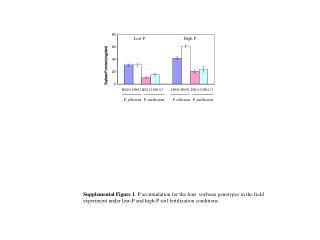
G. Kramberger, charge trappingn-on-n or n-on-p would be better than p-on-n • The trapping time constant at 2.1014cm-2 • of order 13 ns for electrons and 9 ns for holes. • The exact numbers depend on • The composition of the equivalent fluence charged hadrons vs neutrons Simulation of the GTK sensor without edges (Vbias =150V, fluence=21014 , Neff=-41012 cm-3, trapping as mentioned above Red is contribution of holes and blue from electrons, black is the sum WG GTK 23-03-10 pierre jarron
Bias effect What would predominately cause the problem in CCE is the ballistic deficit (trapping reduces CCE~5%) as the induced current pulses can be longer than 4 ns, even with 200 um thick detector. The increase of voltage helps of course (red =150V, black=400 V), but it is close to the limit WG GTK 23-03-10 pierre jarron
Delta ray issue • A problem may be delta rays which would change the shape of the induced current, different pulse shapes for different hit positions • Landau fluctuations, loss of charge due to charge sharing … . • look at simulation in p-on-n strip detector where Ramo field plays an important role • pitch 300 um, implant width 100 um, 400 V the rest the same as before • red is MIP track through the center of the strip, • blue is the same amount of charge deposited but with half of the e-h pairs coming from a delta ray at the back of the detector • black a MIP track near the strip edge. this would make timing with 100 ps difficult. WG GTK 23-03-10 pierre jarron
Capacitance of the hybrid assembly WG GTK 23-03-10 pierre jarron
Capacitance versus pixel pitch WG GTK 23-03-10 pierre jarron
Noise versus pixel size and shaping WG GTK 23-03-10 pierre jarron
Jitter versus pixel pitch WG GTK 23-03-10 pierre jarron
Conclusions Radiation damage study Looks like p-on-n is not the right choice! Radiation damage degrades pulse shape and jitter But… radiation damage plus delta ray is a killer Next Simulation with SPICE based on simulation done by Ljubljana, include pixel geometry Try to understand better delta ray effect Massimiliano’s experimental test and simulation Hybrid capacitance Essentially no surprise Redo simulation with GTK parameters WG GTK 23-03-10 pierre jarron