Download
1 / 30
440 likes | 817 Views
ME 350 – Lecture 8 – Chapter 10. FUNDAMENTALS OF METAL CASTING: Overview of Casting Technology Heating and Pouring Solidification and Cooling. Capabilities and Advantages of Casting. Can create complex part geometries Can create both external and internal shapes

E N D
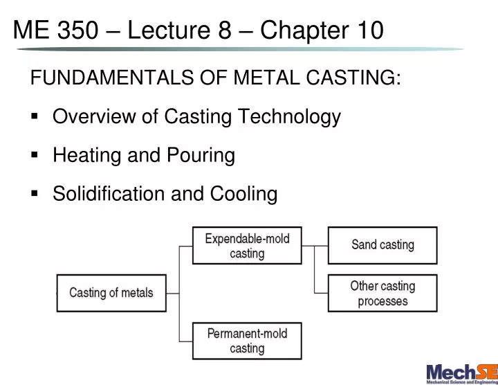
ME 350 – Lecture 8 – Chapter 10 FUNDAMENTALS OF METAL CASTING: • Overview of Casting Technology • Heating and Pouring • Solidification and Cooling
Capabilities and Advantages of Casting • Can create complex part geometries • Can create both external and internal shapes • Some casting processes are net shape; others are near net shape • Can produce a wide variety of sized parts: • Large parts: engine blocks, wood burning stoves, railway wheels, pipes, church bells, statues, etc. • Small parts: dental crowns, jewelry, small statues, frying pans
Limitations of Casting • Limitations on mechanical properties (cold working, heat treating, alloy segregation, etc.) • Poor dimensional accuracy and surface finish for some processes; e.g., sand casting • Safety hazards to workers due to hot molten metals
Two Categories of Casting Processes • Uses a mold which is destroyed to remove casting: • Mold materials: sand, plaster, and similar materials, plus binders • Uses a mold which can be used over and over: • Made of metal (or, less commonly, a ceramic refractory material
Sand Casting Mold Terms • Mold consists of two halves: • Upper half of mold: • Bottom half of mold: • Mold halves are contained in a box, called: • The two halves separate at the: • Gating system consists of: • Horizontal tube openings through which metal travels to the main cavity: • Vertical tube opening of varying diameter designed to control metal flow velocity: • Topmost opening designed to minimize splash and turbulence:
Riser Reservoir in the mold which acts as a source of liquid metal during solidification to: • In order to satisfy its function, the riser must be designed to freeze(before or after) the main casting
Use of a Core in the Mold Cavity • The mold cavity provides the external surfaces of the cast part • In addition, a casting may have internal surfaces, determined by a core, placed inside the mold cavity to define the interior geometry of part • In sand casting, cores are generally made of sand
Heating the Metal • The heat required is the sum of: • Heat to raise temperature to melting point • Heat of fusion to convert from solid to liquid • Heat to raise molten metal to desired temperature for pouring H = ρV{Cs∙(Tm-To) + Hf + Cl ∙(Tp- Tm)} Where, H = total heat for pouring (J) ρ = density (g/cm3) V = volume of metal being heated (cm3) Cs = weight specific heat of solid metal (J/g-C) Tm = melting temperature T0 = starting temperature Hf = Heat of fusion Cl = weight specific heat of liquid metal (J/g-C) Tp = pouring temperature
Molten Metal Flow • Bernoulli’s Theorem – the sum of energies (head, pressure, kinetic, and friction) at any two points in a flowing liquid are equal where, h = head (cm); p = pressure (N/cm2); ρ = density(g/cm3); v = velocity (cm/s); g = gravity (981 cm/s2); F = head loss due to friction (cm) • Ignoring friction and assuming no applied pressure.
Molten Metal Flow (cont’) • Solving for velocity at base of sprue assuming the velocity is negligible: where, h = height of the sprue • Continuity of Flow Law – volume rate of flow is constant: where Q = volumetric flow rate (cm3/s) • Time to fill a mold cavity:
Design of Sprue Taper • To prevent air bubbles from becoming entrapped (aspirated) into the molten metal stream, the sprue diameter is tapered such that the volumetric flow rate remains constant throughout the length of the sprue where, vbottom > vtopthus, Atop > Abottom
Pouring Example The height of a downsprue is 10cm, cross-sectional area at the bottom is 2cm2 (dia.= 1.6cm), at the top 4cm2 (dia.= 2.25cm), and the area of pouring cup is 38.5cm2 (dia.= 7cm) What is the velocity at the bottom of the downsprue? What is the volume flow rate? What is the velocity at the top of the downsprue? What is the vertical flow velocity within the pouring cup?
Turbulence • If the pouring rate is excessive, turbulence can become a serious problem. • A turbulent flow, i.e.: • Increases the amount of metal oxides incorporated in the mold • Causes
Solidification of Metals Transformation of molten metal back into solid state • Solidification differs depending on whether the metal is • A pure element or • An alloy
Solidification of Pure Metals • Due to chilling action of mold wall, a thin skin of solid metal is formed at the interface immediately after pouring • Randomly oriented grains of small size form near the mold wall, and large columnar grains oriented toward the center of the casting form later
Solidification of Alloys • Most alloys freeze over a temperature range rather than at a single temperature Phase diagram and cooling curve for 50%Ni‑50%Cu
Solidification of Alloys Characteristic grain structure in an alloy casting, showing segregation of alloying components in center of casting.
Solidification Time • TTS depends on size and shape of casting by relationship known as Chvorinov's Rule where TTS = total solidification time; V = volume of the casting; A = n = exponent with typical value = 2; Cm = mold constant(determined experimentally)
Mold Constant in Chvorinov's Rule • Mold constant Cm depends on: • Mold material (sand permeability, etc.) • Thermal properties of casting metal • Pouring temperature relative to melting point • Value of Cm for a given casting operation can be based on experimental data from previous operations carried out using same mold material, metal, and pouring temperature, even though the shape of the part may be quite different
What Chvorinov's Rule Tells Us • A casting with a higher volume‑to‑surface area ratio cools and solidifies: • To feed molten metal to the main cavity, TTS for the riser must be than TTS for the main casting • Since mold constants of the riser and casting will be equal, design the riser to solidify last by having its volume-to-area ratio as compared to the main casting: • This minimizes the effects of:
Shrinkage in Solidification and Cooling Shrinkage of a cylindrical casting during solidification and cooling: (0) starting level of molten metal immediately after pouring; (1) reduction in level caused by liquid contraction during cooling (dimensional reductions are exaggerated for clarity).
Shrinkage in Solidification and Cooling (2) reduction in height and formation of shrinkage cavity caused by solidification shrinkage; (3) further reduction in height and diameter due to thermal contraction during cooling of solid metal (dimensional reductions are exaggerated for clarity).
Solidification Shrinkage • Occurs in nearly all metals because the solid phase has a higher density than the liquid phase • Solidification Shrinkage %, α, and Thermal Contraction %, β, for common metals are in Table 10.1 (pg218) • Final metal volume,Vfinal= • Linear dimension change Lfinal= • Exception: cast iron with high carbon content • Graphitization during final stages of freezing causes expansion that counteracts volumetric decrease associated with phase change
Shrinkage Allowance • Patternmakers account for solidification shrinkage and thermal contraction by making mold cavity oversized • Amount by which mold is made larger relative to final casting size is called pattern shrinkage allowance • Casting dimensions are expressed linearly, so allowances are applied accordingly
Directional Solidification • To minimize damaging effects of shrinkage, it is desirable for regions of the casting most distant from the liquid metal supply to freeze first and for solidification to progress from these remote regions toward the • Thus, to prevent shrinkage voids molten metal is continually available from the
Achieving Directional Solidification • Desired directional solidification is achieved using Chvorinov's Rule • Locate sections of the casting with lower V/A ratios away from riser, so freezing occurs first in these regions, and the liquid metal supply for the rest of the casting remains open • Chills ‑ internal or external heat sinks that cause rapid freezing in certain regions of the casting
External Chills (a) External chill to encourage rapid freezing of the molten metal in a thin section of the casting; and (b) the likely result if the external chill were not used.
Riser Design • Riser is waste metal that is separated from the casting and remelted to make more castings • To minimize waste in the unit operation, it is desirable for the volume of metal in the riser to be a minimum • Since the geometry of the riser is normally selected to maximize the V/A ratio, this allows riser volume to be reduced to the minimum possible value