Download
1 / 14
150 likes | 291 Views
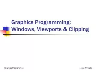
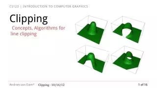
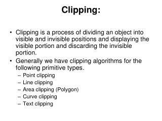
Windows, Viewports, and Clipping. Windows and Viewports. Window. Image Space. Viewport. Information outside the viewport is clipped away. Terminology. World Coordinate System ( Object Space ) - Representation of an object measured in some physical units.

E N D
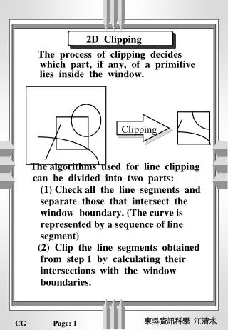
Windows and Viewports Window Image Space Viewport Information outside the viewport is clipped away
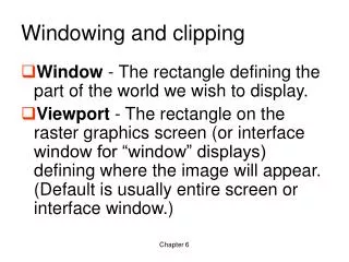
Terminology • World Coordinate System (Object Space) - Representation of an object measured in some physical units. • Window - The rectangle defining the part of the world we wish to display. • Image Coordinate System (Image Space) - The space within the image is displayed • Viewport - The rectangle area in image space where the image from the window will appear. • Viewing Transformation - The process of going from a window in world coordinates to a viewport in image coordinates.
Viewing Transformation Translate to origin Choose Window in World Coordinates Clip to size of Window Scale to size of Viewport Translate to proper position in image
Notes on Viewing Transformation • Panning - Moving the window about the world • Zooming - Reducing the window size • As the window increases in size, the image in the viewport decreases • As the widow decreases in size, the image in the view port increases. • Beware of aspect ratio as the you change the size of the window.
Viewing Transformation Example (10, 30) (50, 30) (0, 239) (160, 239) Viewport wanted (0, 120) (160, 120) (10, 5) (50, 5) X scale = 160/40 = 4 (0,0) (319, 0) 1 0 0 0 1 120 0 0 1 4 0 0 0 4.8 0 0 0 1 1 0 -10 0 1 -5 0 0 1 3) Translate to proper coordinates 2) Scale to correct size 1) Translate window to origin
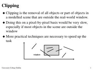
Clipping • A line is visible if both of its end points are in the window. • Brute Force Method - Solve simultaneous equations for intersections of lines with window edges. (xl, yt) (xr, yt) A point is visible if xl < X < xr and yb < Y < yt (xl, yb) (xr, yb)
Cohen-Sutherland Algorithm • Region Checks: Trivially reject or accept lines and points. • Fast for large windows (everything is inside) and for small windows (everything is outside). • Each vertex is assigned a four-bit outcode. • Bit 1 : sign bit of (yt-Y) -- point is above window • Bit 2 : sign bit of (Y-yb) -- point is below window • Bit 3 : sign bit of (xr-X) -- point is to right of window • Bit 4 : sign bit of (X-xl) -- point is to left of window • (if Sign < 0 Bit = 1 else Bit = 0)
Cohen-Sutherland Clipping (cont.) • A line can be trivially accepted if both endpoints have an outcode of 0000. • A line can be trivially rejected if any corresponding bits in the two outcodes are both equal to 1. (This means that both endpoints are to the right, to the left, above, or below the window.) 1001 1000 1010 Bit 1: Above Bit 2: Below Bit 3: Right Bit 4: Left 0001 0000 0010 0101 0100 0110
Clipping Lines Not Accepted or Rejected • In the case where a line can be neither trivially accepted nor rejected, the algorithm uses a “divide and conquer” method. D C B Example: A H E F G Line AD: 1) Test outcodes of A and D --> can’t accept or reject. 2) Calculate intersection point B, which is conceptually on the window side of the dividing line. Form new line segment AB and discard the rest of the line because it is above the window. 3) Test outcodes of A and B. Reject.
Polygon Clipping • Polygons can be clipped against each edge of the window one edge at a time. Window/edge intersections, if any, are easy to find since the X or Y coordinates are already known. • Vertices which are kept after clipping against one window edge are saved for clipping against the remaining edges. Note that the number of vertices usually changes and will often increase.
Polygon Clipping Algorithm • The window boundary determines a visible and invisible region. • The edge from vertex Pi to vertex Pi+1 can be one of four types: • Exit visible region - save the intersection • Wholly outside visible region - save nothing • Enter visible region - save intersection and endpoint • Wholly inside visible region - save endpoint P4 P4 I2 I2 P3 I1 I1 P1 P2 P1
Polygon clipping issues • The final output, if any, is always considered a single polygon. • The spurious edge may not be a problem since it always occurs on a window boundary, but it can be eliminated if necessary.
Pipelined Polygon Clipping • Because clipping against one edge is independent of all others, it is possible to arrange the clipping stages in a pipeline. the input polygon is clipped against one edge and any points that are kept are passed on as input to the next stage of the pipeline. • This way four polygons can be at different stages of the clipping process simultaneously. This is often implemented in hardware. Clip Bottom Clip Top Clip Right Clip Left