Download
1 / 38
380 likes | 387 Views
The SprintIRu00ae-W is a high flow through NDIR<br>CO2 sensor using state-of-the-art solid-state<br>LED optical technology. The low power LEDs<br>are manufactured in-house, giving GSS<br>complete control of the CO2 sensor signal chain

E N D
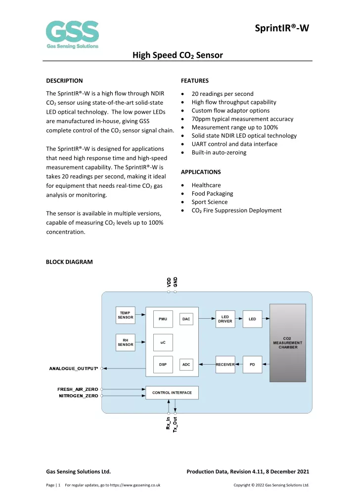
SprintIR®-W High Speed CO2 Sensor DESCRIPTION FEATURES • • • • • • • • The SprintIR®-W is a high flow through NDIR CO2 sensor using state-of-the-art solid-state LED optical technology. The low power LEDs are manufactured in-house, giving GSS complete control of the CO2 sensor signal chain. 20 readings per second High flow throughput capability Custom flow adaptor options 70ppm typical measurement accuracy Measurement range up to 100% Solid state NDIR LED optical technology UART control and data interface Built-in auto-zeroing The SprintIR®-W is designed for applications that need high response time and high-speed measurement capability. The SprintIR®-W is takes 20 readings per second, making it ideal for equipment that needs real-time CO2 gas analysis or monitoring. APPLICATIONS • • • • Healthcare Food Packaging Sport Science CO₂ Fire Suppression Deployment The sensor is available in multiple versions, capable of measuring CO2 levels up to 100% concentration. BLOCK DIAGRAM Gas Sensing Solutions Ltd. Production Data, Revision 4.11, 8 December 2021 Page | 1 For regular updates, go to https://www.gassening.co.uk Copyright © 2022 Gas Sensing Solutions Ltd.
SprintIR®-W High Speed CO2 Sensor TABLE OF CONTENTS DESCRIPTION ........................................................................................................................................... 1 FEATURES ................................................................................................................................................ 1 APPLICATIONS ......................................................................................................................................... 1 BLOCK DIAGRAM ..................................................................................................................................... 1 ORDERING INFORMATION ...................................................................................................................... 4 PACKAGE DRAWING: SprintIR®-W WITH FLOW PORT ADAPTOR ........................................................... 5 PACKAGE DRAWING: SprintIR®-W WITH MEMBRANE COVER ............................................................... 6 PIN-OUT DESCRIPTION: SprintIR®-W (Either Version) ............................................................................ 6 ABSOLUTE MAXIMUM RATINGS ............................................................................................................. 7 RECOMMENDED OPERATING CONDITIONS ............................................................................................ 7 MECHANICAL SEALING – For Sensors with Flow Port Adaptor Only ...................................................... 7 CO2 2 PERFORMANCE CHARACTERISTICS ............................................................................................... 8 HUMIDTY PERFORMANCE CHARACTERISTICS - SprintIR®-W Option ...................................................... 9 TEMPERATURE PERFORMANCE CHARACTERISTICS - SprintIR®-W Option ............................................. 9 CO2 ANALOGUE OUTPUT PERFORMANCE CHARACTERISTICS – SprintIR®-W Option ............................. 9 ELECTRICAL CHARACTERISTICS ............................................................................................................. 10 POWER CONSUMPTION - SprintIR®-W ................................................................................................. 10 INTERFACE TIMING – NITROGEN_ZERO and FRESH_AIR_ZERO ........................................................... 11 RESPONSE TIME, FLOW RATE AND MEASUREMENT RATE - SprintIR®-W ............................................ 12 Measurement Rate ........................................................................................................................... 12 Gas Exchange Rate ............................................................................................................................ 12 Digital Filter Setting ........................................................................................................................... 12 METHOD OF OPERATION ...................................................................................................................... 13 MODE 0 COMMAND MODE .................................................................................................................. 13 MODE 1 STREAMING MODE ................................................................................................................. 13 MODE 2 POLLING MODE ....................................................................................................................... 13 DIGITAL FILTER ...................................................................................................................................... 14 ZERO POINT SETTING ............................................................................................................................ 16 ZERO IN A KNOWN GAS CONCENTRATION ........................................................................................... 16 ZERO IN NITROGEN ............................................................................................................................... 16 ZERO IN FRESH AIR ................................................................................................................................ 16 ZERO POINT ADJUSTMENT .................................................................................................................... 16 AUTO-ZERO FUNCTION ......................................................................................................................... 17 AUTO-ZERO INTERVALS ......................................................................................................................... 17 AUTO-ZERO SETTINGS ........................................................................................................................... 17 PRESSURE AND CONCENTRATION LEVEL COMPENSATION .................................................................. 18 ALTITUDE COMPENSATION TABLE ........................................................................................................ 18 CONTROL INTERFACE ............................................................................................................................ 20 CONTROL INTERFACE TIMING - UART MODE ....................................................................................... 20 UART COMMAND PROTOCOL ............................................................................................................... 20 UART OPERATION ................................................................................................................................. 20 UART INTERFACE SUMMARY ................................................................................................................ 21 Gas Sensing Solutions Ltd. Page | 2 For regular updates, go to https://www.gassening.co.uk Production Data, Revision 4.11, 8 December 2021 Copyright © 2022 Gas Sensing Solutions Ltd.
SprintIR®-W High Speed CO2 Sensor CO2 LEVEL MEASUREMENT VALUE - Z INFORMATION (0x5A) .............................................................. 23 CO2 LEVEL MEASUREMENT VALUE - z INFORMATION (0x7A) .............................................................. 23 ‘.’ COMMAND (0x2E) ......................................................................................................................... 23 TEMPERATURE MEASUREMENT VALUE - SprintIR®-W Option ............................................................. 24 HUMIDITY MEASUREMENT VALUE - SprintIR®-W Option .................................................................... 24 CO2 ANALOGUE OUTPUT COMMAND ............................................................................................... 25 K COMMAND ......................................................................................................................................... 26 K COMMAND (0x4B) ......................................................................................................................... 26 DIGITAL FILTER COMMANDS ................................................................................................................ 27 A COMMAND (0x41) ......................................................................................................................... 27 a COMMAND (0x61) .......................................................................................................................... 27 ZERO POINT SETTING COMMANDS ...................................................................................................... 28 F COMMAND (0x46) .......................................................................................................................... 28 G COMMAND (0x47) ......................................................................................................................... 29 U COMMAND (0x55) ......................................................................................................................... 29 u COMMAND (0x75) ......................................................................................................................... 29 X COMMAND (0x58) ......................................................................................................................... 29 P COMMAND - CO2 Level for Auto-Zeroing ...................................................................................... 29 P COMMAND – CO2 Level for Zero-Point Setting .............................................................................. 30 AUTO-ZEROING INTERVALS .................................................................................................................. 31 @ COMMAND (0x40) ........................................................................................................................ 31 PRESSURE AND CONCENTRATION COMPENSATION ............................................................................ 32 S COMMAND (0x53) .......................................................................................................................... 32 s COMMAND (0x73) .......................................................................................................................... 32 MEASUREMENT DATA OUTPUTS .......................................................................................................... 33 M COMMAND ................................................................................................................................... 34 Q COMMAND .................................................................................................................................... 34 SERIAL NUMBER AND FIRMWARE VERSION ......................................................................................... 35 Y COMMAND (0x59) .......................................................................................................................... 35 CONNECTION DIAGRAM FOR UART INTERFACE ................................................................................... 36 IMPORTANT NOTICE ............................................................................................................................. 37 ADDRESS ............................................................................................................................................... 37 Gas Sensing Solutions Ltd. Page | 3 For regular updates, go to https://www.gassening.co.uk Production Data, Revision 4.11, 8 December 2021 Copyright © 2022 Gas Sensing Solutions Ltd.
SprintIR®-W High Speed CO2 Sensor ORDERING INFORMATION SPRINTIR-W-X-XXX-X Measurement Range X 5 20 60 100 0-5% 0-20% 0-60% 0-100% X Temperature Range E Extended, -25 to 55°C 0 to 50°C Blank Flow Adaptor X F Included Not included Blank X Temperature and RH H X Included Not included X CO2 Voltage Output Included Not included V X Notes: 1.Sensors are shipped individually 2.Custom flow through adaptors are available, contact GSS for options See separate data sheet for SprintIR®-W evaluation kit options. Gas Sensing Solutions Ltd. Page | 4 For regular updates, go to https://www.gassening.co.uk Production Data, Revision 4.11, 8 December 2021 Copyright © 2022 Gas Sensing Solutions Ltd.
SprintIR®-W High Speed CO2 Sensor PACKAGE DRAWING: SprintIR®-W WITH FLOW PORT ADAPTOR Top View Weight = ~7g Gas Sensing Solutions Ltd. Page | 5 For regular updates, go to https://www.gassening.co.uk Production Data, Revision 4.11, 8 December 2021 Copyright © 2022 Gas Sensing Solutions Ltd.
SprintIR®-W High Speed CO2 Sensor PACKAGE DRAWING: SprintIR®-W WITH MEMBRANE COVER Top View Weight = ~6g PIN-OUT DESCRIPTION: SprintIR®-W (Either Version) PIN 1 2 3 4 5 6 7 8 NAME GND NC VDD GND Rx_In GND Tx_Out NITROGEN_ZERO TYPE Supply Unused Supply Supply Digital Input Supply Digital Output Digital Input DESCRIPTION Sensor ground Do Not Connect Sensor supply voltage Sensor ground UART Receive Input Sensor ground UART Transmit Output Set low to initiate a Zero in Nitrogen Setting Cycle CO2 Level (Optional) Set low to initiate a Zero in Fresh Air Setting Cycle 9 10 ANALOGUE_OUTPUT Analogue Output FRESH_AIR_ZERO Digital Input Gas Sensing Solutions Ltd. Page | 6 For regular updates, go to https://www.gassening.co.uk Production Data, Revision 4.11, 8 December 2021 Copyright © 2022 Gas Sensing Solutions Ltd.
SprintIR®-W High Speed CO2 Sensor ABSOLUTE MAXIMUM RATINGS Absolute Maximum Ratings are stress ratings only. Permanent damage to the SprintIR®-W may be caused by continuously operating at or beyond these limits. The SprintIR®-Wfunctional operating limits and guaranteed performance specifications are given at the test conditions specified. ESD Sensitive Device. This sensor uses ESD sensitive components. It is therefore generically susceptible to damage from excessive static voltages. Proper ESD precautions must be taken during handling and storage of this device. CONDITION Supply Voltages Voltage Range Digital Inputs Operating Temperature Range (Ta) - Standard Storage Temperature Range Humidity Range (RH), Non- Condensing Operating Ambient Pressure Range MIN -0.3V GND -0.3V 0°C -40°C 0 MAX +6.0V 5V +50°C +70°C 95% 500mbar 2bar RECOMMENDED OPERATING CONDITIONS PARAMETER Supply Ground SYMBOL VDD GND MIN 3.25 TYP 3.3 0 MAX 5.5 UNIT V V MECHANICAL SEALING – For Sensors with Flow Port Adaptor Only CONDITION Working Pressure1 Burst Pressure2 MIN 0.3bar 2bar MAX Test Conditions Unless Otherwise Specified 1. The mechanical sealing between the flow adaptor and sensor housing is tested by pressurising the gas chamber to 0.3bar. The pressure reading must not drop by more than 1mbar within 30 seconds Guaranteed by design, not tested Sensors with a membrane cover do not have an air-tight seal between the sensor casing and the main sensor body. 2. 3. Gas Sensing Solutions Ltd. Page | 7 For regular updates, go to https://www.gassening.co.uk Production Data, Revision 4.11, 8 December 2021 Copyright © 2022 Gas Sensing Solutions Ltd.
SprintIR®-W High Speed CO2 Sensor CO2 2 PERFORMANCE CHARACTERISTICS Test Conditions Unless Otherwise Specified VDD = 3.3V, GND = 0V. CO2 = 450ppm, RH = 0% non-condensing, T= 25°C, Pressure = 1013mbar, Flow Rate = 0.2l/minute, Flow Port PARAMETER SYMBOL TEST CONDITIONS MIN TYP MAX UNIT 0 5 CO2 measurement range % % % % 0 20 0 60 0 100 @25°C ±(70 +5%rdg) ±(70 +5%rdg +~0.1%rdg per °C) ±(300 +5%rdg) ±(300 +5%rdg +~0.1% per °C) 6 Accuracy (Peak-Peak) 0-60% ppm 0°C to +50°C, after auto-zero @25°C ppm @25°C Accuracy (Peak-Peak) 0-100% ppm 0°C to +50°C, after auto-zero @25°C ppm Digital filter setting 16 CO2 RMS Noise Time to Valid Measurement After Power-On Response Time ppm secs First value from sensor 0.3 T90, no filter @ 0.1l/min T90, filter = 16 @ 0.1l/min @25°C, 0-60% 3.6 secs 4.8 ±(70 +5%rdg) ±(300 +5%rdg) 35 Repeatability ppm @25°C, 0-100% ppm Peak current when sampling Peak at turn-on Current Consumption mA 40 mA mA SLEEP Mode (K 0 commnad) 0.01 Gas Sensing Solutions Ltd. Page | 8 For regular updates, go to https://www.gassening.co.uk Production Data, Revision 4.11, 8 December 2021 Copyright © 2022 Gas Sensing Solutions Ltd.
SprintIR®-W High Speed CO2 Sensor HUMIDTY PERFORMANCE CHARACTERISTICS - SprintIR®-W Option PARAMETER SYMBOL TEST CONDITIONS MIN TYP MAX UNIT Humidity measurement range Accuracy 0 100 % @25°C ±3 % RH @25°C Repeatability Response time Accuracy drift ±1 <8 0.25 % 0-50% secs % RH/Yr TEMPERATURE PERFORMANCE CHARACTERISTICS - SprintIR®-W Option PARAMETER SYMBOL TEST MIN TYP MAX UNIT CONDITIONS Temperature measurement range Accuracy -25 55 °C 0-50°C ±0.5 °C @25°C Repeatability Response time Accuracy drift ±0.1 >10 0.03 % 0-50%, @25°C secs %/Yr CO2 ANALOGUE OUTPUT PERFORMANCE CHARACTERISTICS – SprintIR®-W Option PARAMETER SYMBOL TEST CONDITIONS MIN TYP MAX UNIT Output voltage range1, 2 ANALOGUE_OUTPUT 0 VDD V CO2 level 0-5%, VDD 3.3V 0-20%, VDD 3.3V 0-60%, VDD 3.3V 0-100%, VDD 3.3V @25°C, 0-60% 66 uV/ppm 16.5 uV/ppm 5.5 uV/ppm 3.3 uV/ppm Repeatability Response time ±0.1 ±0.1 0.5 % % @25°C, 0-100% From 0ppm to T50 default settings secs Gas Sensing Solutions Ltd. Page | 9 For regular updates, go to https://www.gassening.co.uk Production Data, Revision 4.11, 8 December 2021 Copyright © 2022 Gas Sensing Solutions Ltd.
SprintIR®-W High Speed CO2 Sensor Notes 1.The output CO2 accuracy is degraded where ANALOGUE_OUTPUT <50mV, or >VDD–50mV 2.ANALOGUE_OUTPUT accuracy specified with a resistive loading @ >100Kohm ELECTRICAL CHARACTERISTICS PARAMETER SYMBOL TEST MIN TYP MAX UNIT CONDITIONS Digital Input/Output Input HIGH Level Input LOW Level Output HIGH Level Output LOW Level IOH = +1mA IOL = -1mA 1.8 2.6 V V V V 1.0 3.0 0.4 POWER CONSUMPTION - SprintIR®-W Test Conditions Unless Otherwise Specified VDD = 3.3V, GND = 0V. CO2 = 450ppm, RH = 0% non-condensing, T= 25°C, Pressure = 1013mbar, Flow Rate = 0.2l/minute SETTING SYMBOL TEST CONDITIONS VDD Total Power mW 0.03 V 3.3 I (mA) 0.01 Active, K0 SLEEP mode, no measurement Active, K1 mode whilst taking measurements Additional Power with RH active Additional Power with T active Additional Power with CO2 active Default settings 3.3 9 30 RH measurement on 3.3 0.05 0.2 Temperature measurement on With analogue CO2 output 3.3 0.05 0.2 3.3 0.02 0.1 Gas Sensing Solutions Ltd. Page | 10 For regular updates, go to https://www.gassening.co.uk Production Data, Revision 4.11, 8 December 2021 Copyright © 2022 Gas Sensing Solutions Ltd.
SprintIR®-W High Speed CO2 Sensor INTERFACE TIMING – NITROGEN_ZERO and FRESH_AIR_ZERO VDD t2 t1 NITROGEN_ZERO t3 CONTROL INTERFACE PARAMETER Power On to NITROGEN_ZERO Ready NITROGEN_ZERO Low Pulse-Width Control Interface Setup Time SYMBOL t1 MIN Time to stable gas 3 600 TYP MAX UNIT s t2 t3 s ns Notes 1.The timing for FRESH_AIR_ZERO is identical to NITROGEN_ZERO 2.Ensure gas concentration is stable (t1) before beginning zeroing process Gas Sensing Solutions Ltd. Page | 11 For regular updates, go to https://www.gassening.co.uk Production Data, Revision 4.11, 8 December 2021 Copyright © 2022 Gas Sensing Solutions Ltd.
SprintIR®-W High Speed CO2 Sensor RESPONSE TIME, FLOW RATE AND MEASUREMENT RATE - SprintIR®-W The SprintIR®-W response time is dependent on several interrelated factors. Measurement Rate The measurement rate is fixed at 20 readings per second. Gas Exchange Rate The most important factor is the gas exchange rate. This is the amount of time it takes for the gas to enter the CO2 measurement chamber, measured, and then replaced. The sensor has a gas measurement chamber volume of approximately 2.8ml. As a general rule of thumb, to properly exchange the gas in the chamber, there needs to be a x5 volume of gas passed through the sensor. Therefore, approximately 14ml of gas needs to flow through the sensor for each reading. (/) =/ ∗ ∗ Digital Filter Setting The sensor outputs both filtered and raw unfiltered CO2 readings. If the filtered measurement data is used, the read rate will also depend on the filter setting or the algorithm to process the raw data. The table below shows how the response time varies with filter setting and flow rate. Gas delivery Measurement frequency (Hz) 20 T50 Response time 0.1l/min (s) T50 Response time 1l/min (s) No filter Filter 16 0.7s 1.5s No filter 0.1s Filter 16 1.3s Flow Adaptor Gas delivery Measurement frequency (Hz) 20 T90 Response time 0.1l/min (s) T90 Response time 1l/min (s) No filter Filter 16 3.6s 4.8s No filter 0.3s Filter 16 2.5s Flow Adaptor Gas Sensing Solutions Ltd. Page | 12 For regular updates, go to https://www.gassening.co.uk Production Data, Revision 4.11, 8 December 2021 Copyright © 2022 Gas Sensing Solutions Ltd.
SprintIR®-W High Speed CO2 Sensor METHOD OF OPERATION After power is applied to the SprintIR®-W, the sensor will automatically start to take CO2 measurements using the Mode 1 default settings, where the sensor is pre-programmed to send CO2 measurement data at 20 readings per second. The measurement rate is fixed at 20 readings per second at a fixed 9600 baud rate. The sensor will return the previous CO2 measurement results if the user requests more frequent measurements. The SprintIR®-W has 3 potential modes of operation. MODE 0 COMMAND MODE In this mode, the sensor is in a SLEEP mode, waiting for commands. No measurements are made. There is no latency in command responses. All commands that report measurements or alter the zero-point settings are disabled in Mode 0. Mode 0 is NOT retained after power cycling. MODE 1 STREAMING MODE This is the factory default setting. Measurements are reported 20 per second. Commands are processed when received, except during measurement activity, so there may be a time delay of up to 10ms in responding to commands. MODE 2 POLLING MODE In polling mode, the sensor only reports readings when requested. The sensor will continue to take measurements in the background, but the output stream is suppressed until data is requested. The sensor will always power up in streaming or polling mode, whichever mode was used before the power cycle. Gas Sensing Solutions Ltd. Page | 13 For regular updates, go to https://www.gassening.co.uk Production Data, Revision 4.11, 8 December 2021 Copyright © 2022 Gas Sensing Solutions Ltd.
SprintIR®-W High Speed CO2 Sensor DIGITAL FILTER The CO2 gas chamber is illuminated with a nominal 4.25um wavelength LED and the signal received using a photodiode. The signal from the photodiode is processed and filtered by the sensor to remove noise and provide an accurate CO2 reading. High frequency noise coming from the sampling process is removed using a proprietary lowpass filter. The digital filter setting can be varied, allowing the user to reduce measurement noise at the expense of the measurement response time. The ideal digital filter setting is application specific and is normally a balance between CO2 reading accuracy and response time. The SprintIR®-W sensor will also output the raw unfiltered CO2 measurement data. This data can be post processed using alternative filter algorithms. Filter Effect on Measurement Data Outputs 900 800 700 600 CO2 Levels (ppm) 500 400 Filtered (Z) 300 Unfiltered (z) 200 100 0 1 11 21 31 41 51 # Measurements The graph above shows the effects of the filter on the CO2 measurement data (Z or z). The unfiltered output is shown in orange and the filtered output shown in blue. Filter Response vs. Filter Setting 4500 4000 3500 A=16 3000 A=32 CO2 Level (ppm) A=64 2500 A=128 2000 T90 1500 1000 500 0 0 50 100 150 200 250 300 350 400 # Measurements The graph above shows the effect of the filter on response times. Increasing the filter setting increases the measurement output response time. T90 is the time to 90% of reading. The SprintIR®- W takes 20 readings per second. The flow rate was set at 0.2l/min. Gas Sensing Solutions Ltd. Page | 14 For regular updates, go to https://www.gassening.co.uk Production Data, Revision 4.11, 8 December 2021 Copyright © 2022 Gas Sensing Solutions Ltd.
SprintIR®-W High Speed CO2 Sensor Sampling noise is progressively reduced with higher digital filter settings. It is recommended the user sets the highest value digital filter setting without compromising the required flow rate. Flow Rate Recommended Digital Filter Setting ‘a’ 0.1litre/minute 64 0.5litre/minute 32 1litre/minute 16 5litre/minute 8 Gas Sensing Solutions Ltd. Page | 15 For regular updates, go to https://www.gassening.co.uk Production Data, Revision 4.11, 8 December 2021 Copyright © 2022 Gas Sensing Solutions Ltd.
SprintIR®-W High Speed CO2 Sensor ZERO POINT SETTING There are a several methods available to the user to set the zero point of the sensor. The recommended method is zero-point setting in a known gas concentration. In all cases, the best zero is obtained when the gas concentration is stable, and the sensor is at a stabilised temperature. Note that zero-point settings are not cumulative and only the latest zero-point setting is effective. For example, there is no benefit in zeroing in nitrogen, and then zeroing in a calibration gas. The sensor will store only the latest zero point. To improve zeroing accuracy, the recommended digital filter setting is 32. See the ‘A’ command. ZERO IN A KNOWN GAS CONCENTRATION Place the sensor in a known gas concentration, power up the sensor and allow time for the sensor temperature to stabilise, and for the gas to be fully diffused into the sensor. Send the ZERO IN A KNOWN GAS CONCENTRATION command X to the sensor. The sensor will be zeroed using the known gas concentration level sent by the user. The concentration value written to the sensor must be scaled dependent on the sensor CO2 measurement range. The multiplier for the scaling factor is set according to the range of the sensor, see the ‘.’ command. ZERO IN NITROGEN Place the sensor in nitrogen gas and allow time for the sensor temperature to stabilise and the gas to be fully diffused into the sensor. Send the ZERO IN NITROGEN command U to the sensor. The sensor is calibrated assuming a 0ppm CO2 environment. ZERO IN FRESH AIR If there is no calibration gas or nitrogen available, the sensor zero point can be set in fresh air. Ambient CO2 concentrations in fresh air are typically 400ppm. The CO2 concentration fresh air zero level is programmable over a range from 0ppm to the full scale of the sensor. Place the sensor in a fresh air environment and allow time for the sensor temperature to stabilise, and for the fresh air to be fully diffused into the sensor. Power up the sensor, write the G command to the sensor. The concentration value written to the sensor must be scaled dependent on the sensor CO2 measurement range. The sensor can use the default fresh air CO2 concentration value (400ppm), or the user can write a different fresh air value to the sensor if desired. ZERO POINT ADJUSTMENT If the CO2 concentration and the sensor reported concentration are known, the zero point can be adjusted using the known concentration to fine tune the zero point. For example, if the sensor has been in an environment that has been exposed to outside air, and the sensor reading is known at Gas Sensing Solutions Ltd. Page | 16 For regular updates, go to https://www.gassening.co.uk Production Data, Revision 4.11, 8 December 2021 Copyright © 2022 Gas Sensing Solutions Ltd.
SprintIR®-W High Speed CO2 Sensor that time, the zero point can be fine-tuned to correct the reading. This is typically used to implement automated zeroing routines. The known CO2 concentration value and the reported CO2 value from the sensor can be sent to the sensor using the ZERO POINT ADJUSTMENT command F. AUTO-ZERO FUNCTION The sensor has a built-in auto-zeroing function. In order to function correctly, the sensor must be exposed to typical background levels (400-450ppm) at least once during the auto-zeroing period. For example, many buildings will drop quickly to background CO2 levels when unoccupied overnight or at weekends. The auto-zeroing function uses the information gathered during these periods to re-zero. The sensor will reset the ‘zero’ level every time it does an auto-zero. Auto-zeroing is disabled by default. If the sensor is powered down, the auto-zero is reset to default values. The auto-zero function works in the same way as the ZERO IN FRESH AIR command. Auto-zeroing is disabled by default, but can be enabled to operate automatically, or zeroing can be forced. The user can also independently adjust the CO2 level used for auto-zeroing. Typically, it is set to the same value as the ZERO IN FRESH AIR value, but it can also be set at a different level if desired. AUTO-ZERO INTERVALS The auto-zeroing period can be programmed by the user. The sensor can be programmed to undertake an initial auto-zero after power-on. Thereafter, the auto-zero period can be set independently of the start-up zeroing time. Note, the auto zeroing timer is reset if the sensor is powered down. AUTO-ZERO SETTINGS The sensor will automatically ‘zero’ using the measured CO2 level sampled during the auto-zeroing period. The user can alter the behaviour of the sensor as a result of the auto-zero process. Gas Sensing Solutions Ltd. Page | 17 For regular updates, go to https://www.gassening.co.uk Production Data, Revision 4.11, 8 December 2021 Copyright © 2022 Gas Sensing Solutions Ltd.
SprintIR®-W High Speed CO2 Sensor PRESSURE AND CONCENTRATION LEVEL COMPENSATION NDIR gas sensors detect the concentration of gas by measuring the degree of light absorption by the gas analyte. The degree of light absorption is converted into a concentration reported by the sensor. The absorption process is pressure and gas concentration dependent. In general, as the pressure increases, the reported gas concentration also increases. As the pressure decreases, the reported concentration decreases. This effect takes place at a molecular level and is common to all NDIR gas sensors. GSS sensors are calibrated at 1013mbar and 450ppm CO2. The reading will vary due to pressure and CO2 concentration. It is possible to correct for the effects of pressure and concentration by setting a compensation value. This will apply a permanent correction to the output of the sensor, depending on the compensation value. The compensation value needs to be written to the sensor and will overwrite the default 1013mbar and 450ppm CO2 value. The new compensation value will be used for all subsequent measurements and will be retained after a power cycle. ALTITUDE COMPENSATION TABLE Altitude (ft.) Altitude (m) Pressure (mbar) Sea Level Difference % Compensation Value CO2 Change per Measurement Change (%) 0 3 5 7 10 12 15 17 19 22 24 28 32 36 40 44 0 0 1,013 995 977 960 942 925 908 891 875 859 843 812 782 753 724 697 0 18 36 53 71 88 105 122 138 154 170 201 231 260 289 316 0.14 0.14 0.14 0.14 0.14 0.14 0.14 0.14 0.14 0.14 0.14 0.14 0.14 0.14 0.14 0.14 8,192 8,398 8,605 8,800 9,006 9,201 9,396 9,591 9,775 9,958 10,142 10,497 10,841 11,174 11,506 11,816 500 1,000 1,500 2,000 2,500 3,000 3,500 4,000 4,500 5,000 6,000 7,000 8,000 9,000 10,000 153 305 458 610 763 915 1,068 1,220 1,373 1,525 1,830 2,135 2,440 2,745 3,050 Other compensation values can be calculated using the following formula. = + � ∗ . � ∗ Gas Sensing Solutions Ltd. Page | 18 For regular updates, go to https://www.gassening.co.uk Production Data, Revision 4.11, 8 December 2021 Copyright © 2022 Gas Sensing Solutions Ltd.
SprintIR®-W High Speed CO2 Sensor The pressure compensation values calculated above are only approximate and only valid for concentrations below 1%. For higher accuracy compensation, the sensor output must be adjusted for both pressure and concentration as the CO2 level measured by the sensor is affected by both ambient pressure and gas concentration levels. To calculate the adjusted CO2 level, use the following calculation. Corrected CO2 Value =2 (1) 1 +(1013 − ) where, C1 = Concentration reading from sensor P = Pressure in mbar Where concentration is < 1500ppm. Y = 2.6661 × 10−1614− 1.1146 × 10−1213+ 1.7397 × 10−912− 1.2556 × 10−61− 9.8754 × 10⁻⁴ Where concentration is >1500ppm. Y = 2.811 × 10−3816− 9.817 × 10−3215+ 1.304 × 10−2514− 8.126 × 10−2013+ 2.311 × 10−1412 − 2.195 × 10−91− 1.471 × 10⁻³ Gas Sensing Solutions Ltd. Page | 19 For regular updates, go to https://www.gassening.co.uk Production Data, Revision 4.11, 8 December 2021 Copyright © 2022 Gas Sensing Solutions Ltd.
SprintIR®-W High Speed CO2 Sensor CONTROL INTERFACE The SprintIR® family of sensors are controlled by writing and reading from the sensor via its UART interface. The Rx_In and Tx_Out pins are normally high, suitable for direct connection to a UART. If the sensor is to be read by a true RS232 device (e.g. a PC), it is necessary to pass through a level converter to step up/down the voltage and invert the signal. CONTROL INTERFACE TIMING - UART MODE PARAMETER Baud Rate Data Bits Parity Stop Bits Hardware Flow Control SYMBOL MIN TYP 9600 8 None 1 None MAX UNIT Bits/s UART COMMAND PROTOCOL All UART commands must be terminated with a carriage return and line feed <CR><LF>, hex 0x0D 0x0A. In this document, this is shown as ‘\r\n’. UART commands that take a parameter always have a space between the letter and the parameter. The sensor will respond with a ‘?’ if a command is not recognised. The two most common causes are missing spaces or missing <CR><LF> terminators. All command communications are in ASCII and are terminated by carriage return, line feed (0x0D 0x0A). This document uses the protocol “\r\n” to indicate the carriage return line feed. All responses from the sensor, including measurements, have a leading space (ASCII character 32). The character ‘#’ represents an ASCII representation of a numeric character (0-9). Note there is a space between the first letter and any parameter. For example, the X command reads “X space 2000 carriage return line feed”. UART OPERATION When initially powered, the sensor will immediately start to transmit a CO2 reading on receiving any character. The CO2 measurement is reported as: Z #####\r\n whereZ #####shows the CO2 concentration. Note that all outputs from the sensor have a leading space. Gas Sensing Solutions Ltd. Page | 20 For regular updates, go to https://www.gassening.co.uk Production Data, Revision 4.11, 8 December 2021 Copyright © 2022 Gas Sensing Solutions Ltd.
SprintIR®-W High Speed CO2 Sensor UART INTERFACE SUMMARY Syntax A ###\r\n Use Set value of the digital filter Return the value of the digital filter Fine Tune the zero point Zero-point setting using fresh air Returns the relative humidity value Switches the sensor between different modes Sets the number of measurement data types output by the sensor Sets the CO2 reading for maximum voltage output level Example A 32\r\n Response A 00032\r\n Comments See “Digital Filter” a\r\n a\r\n a 00128\r\n See “Digital Filter” F ##### #####\r\n F 410 400\r\n F 33000\r\n See “Zero Point Setting” See “Zero Point Setting” G\r\n G\r\n G 33000\r\n H\r\n H 00551\r\n K #\r\n K 1\r\n K 00001\r\n M #####\r\n M 6\r\n M 00006\r\n See “Measurement Data Outputs” P 0 ###\r\n P 1 #\r\n P 0 19\r\n P 1 136\r\n P 00000 00019\r\n P 00001 00136\r\n Two byte value, P 0 = MSB P 1 = LSB 5000ppm in the example Two-byte value, P 8 = MSB P 9 = LSB 400ppm in the example Two-byte value, P 10 = MSB P 11 = LSB 400ppm in the example P 8 ###\r\n P 9 #\r\n Sets value of CO2 background concentration in ppm for auto-zeroing P 8 1\r\n P 9 144\r\n P 00008 00001\r\n P 00009 00144\r\n P 10 ###\r\n P 11 #\r\n Sets value of CO2 background concentration in ppm used for zero-point setting in fresh air. P 10 1\r\n P 11 144\r\n P 00010 00001\r\n P 00011 00144\r\n Q\r\n Reports the latest measurement data types, as defined by ‘M’ Sets the pressure and concentration compensation value Returns the pressure and concentration compensation value Returns the temperature value Zero-point setting using nitrogen Q\r\n H 12345 T 12345 Z 00010\r\n S #####\r\n S 8192\r\n S 08192\r\n See “Pressure and Concentration Compensation” See “Pressure and Concentration Compensation” s\r\n s\r\n s 08192\r\n T\r\n T 01224\r\n U\r\n U\r\n U 33000\r\n See “Zero Point Setting” Gas Sensing Solutions Ltd. Page | 21 For regular updates, go to https://www.gassening.co.uk Production Data, Revision 4.11, 8 December 2021 Copyright © 2022 Gas Sensing Solutions Ltd.
SprintIR®-W High Speed CO2 Sensor Example Manual setting of the zero point. Zero-point setting using a known gas calibration Return firmware version and sensor serial number Return the most recent filtered CO2 measurement in ppm Return the most recent unfiltered CO2 measurement in ppm Sets the timing for initial and interval auto-zeroing periods Returns the auto- zeroing configuration Switch auto-zeroing on or off Returns the scaling factor multiplier required to convert the Z or z output to ppm Syntax u #####\r\n Use Response u 32997\r\n Comments See “Zero Point Setting” See “Zero Point Setting” u 32997\r\n X #####\r\n X 2000\r\n X 32997\r\n Y\r\n Y\r\n Returns two lines Z\r\n Z\r\n Z 01521\r\n z\r\n z\r\n Z 01521\r\n @ #.# #.#\r\n @ 1.0 8.0\r\n @ 1.0 8.0\r\n See “Auto-zeroing” for details @\r\n @ 1.0 8.0\r\n @ 1.0 8.0\r\n See “Auto-zeroing” for details See “Auto-zeroing” for details Multiply by 10 in the example @ 0\r\n @ 0\r\n @ 0\r\n .\r\n .\r\n . 00010\r\n Gas Sensing Solutions Ltd. Page | 22 For regular updates, go to https://www.gassening.co.uk Production Data, Revision 4.11, 8 December 2021 Copyright © 2022 Gas Sensing Solutions Ltd.
SprintIR®-W High Speed CO2 Sensor CO2 LEVEL MEASUREMENT VALUE - Z INFORMATION (0x5A) Description Syntax Example Response Reports the latest filtered CO2 measurement ASCII Character 'Z', terminated by 0x0D 0x0A (CR & LF) Z\r\n Z 00521\r\n This value needs to be multiplied by the appropriate scaling factor to derive the ppm value. See the ‘.’ command. CO2 LEVEL MEASUREMENT VALUE - z INFORMATION (0x7A) The sensor is also capable of reporting the real time unfiltered CO2 measurement value. Description Syntax Example Response Reports the unfiltered CO2 measurement ASCII Character 'Z', terminated by 0x0D 0x0A (CR & LF) z\r\n z 00521\r\n ‘.’ COMMAND (0x2E) To calculate the measurement value in ppm, the ‘Z’ or ‘z’ value, they must be converted into ppmby using the ‘.’ multiplier factor. This multiplier will depend on the full-scale measurement range of the sensor. The multiplier is related to the full-scale range of the sensor. The multiplier must also be used when sending CO2 concentration levels to the sensor, for example when setting the fresh air CO2 concentration value. The ‘.’ Command can also be used to read back the scaling factor. For example, if the user wants to zero the sensor in a known concentration of gas (e.g. 450ppm), the value written to the sensor must be 450/scaling factor. Description Returns a number indicating what multiplier must be applied to the Z CO2 measurement output to convert it into ppm. ASCII character '.', terminated by 0x0D 0x0A ( CR & LF ) .\r\n . 00010\r\n (this number is variable, usually 10) Syntax Example Response Measurement Range of Sensor CO2 Measurement Scaling Factor (Z) CO2 Measurement Output Units Example 0 – 60% 10 ppm/10 Z 01200 = 12,000ppm = 1.2% 0 – 100% 100 ppm/100 Z 01500 = 150,000ppm = 15% Gas Sensing Solutions Ltd. Page | 23 For regular updates, go to https://www.gassening.co.uk Production Data, Revision 4.11, 8 December 2021 Copyright © 2022 Gas Sensing Solutions Ltd.
SprintIR®-W High Speed CO2 Sensor TEMPERATURE MEASUREMENT VALUE - SprintIR®-W Option Command Use Example Response Comments T\r\n T #####\r\n T 01224\r\n Where ##### is a 5-digit number. Temperature (°C) = (##### - 1000)/10. Returns the most recent temperature measurement. 22.4°C in the example Description Syntax Example Response Returns the most recent temperature measurement. ASCII character 'T', SPACE, decimal, terminated by 0x0D 0x0A ( CR & LF ) T\r\n T 01224\r\n (this number is variable) HUMIDITY MEASUREMENT VALUE - SprintIR®-W Option Command Use Example Response Comments H\r\n H #####\r\n H 00551\r\n Where ##### is a 5-digit number. Humidity (%RH) = #####/10. Return the most recent humidity measurement. 55.1% RH in the example Description Syntax Example Response Returns the most recent the humidity measurement. ASCII character 'H', SPACE, decimal, terminated by 0x0D 0x0A ( CR & LF ) H\r\n H 00551\r\n (this number is variable) Note both temperature and humidity outputs are a factory fit option on the SprintIR®-W only. If not fitted, sensor will return either T 00000 or H 00000. The sensor default data output is filtered CO2 only. To output temperature, humidity, and filtered CO2, send “M 4164\r\n” (see “Measurement Data Outputs”). The output format will have the form: H 00345 T 01195 Z 00065\r\n This example indicates 34.5% RH, 19.5°C and 650ppm CO2. Gas Sensing Solutions Ltd. Page | 24 For regular updates, go to https://www.gassening.co.uk Production Data, Revision 4.11, 8 December 2021 Copyright © 2022 Gas Sensing Solutions Ltd.
SprintIR®-W High Speed CO2 Sensor CO2 ANALOGUE OUTPUT COMMAND Description Sets the CO2 reading for maximum voltage output level. Typically set to sensor full scale value. Value is scaled by CO2 value multiplier, see ‘.’ command. ASCII character 'P', SPACE, then 0, SPACE, then MSB terminated by 0x0D 0x0A (CR & LF) ASCII character 'P' then a space, then 1, then a space, then LSB terminated by 0x0D 0x0A (CR & LF) P 0 19\r\n P 1 136\r\n P 00000 00019\r\n P 00001 00136\r\n Syntax Example Response The value is entered as a two-byte word, MSB first. MSB = Integer (Scale/256) LSB = Scale – (256*MSB) In the above example, the scale is being set to 5000ppm MSB = Integer (5000/256) = 19 LSB = 5000 – (256*19) = 136 The analogue output is turned ON when a valid output value is set. To turn off the analogue output, set P0 and P1 to zero. Gas Sensing Solutions Ltd. Page | 25 For regular updates, go to https://www.gassening.co.uk Production Data, Revision 4.11, 8 December 2021 Copyright © 2022 Gas Sensing Solutions Ltd.
SprintIR®-W High Speed CO2 Sensor K COMMAND The SprintIR®-W has 3 potential modes of operation, controlled by the K command. Mode Mode 0 K=0 Value Description Sleep Mode Sensor is in a SLEEP mode, waiting for commands. No measurements are made. There is no latency in command responses. All commands that report measurements or alter the zero-point settings are disabled in Mode 0. Mode 0 is NOT retained after power cycling. This is the factory default setting. Measurements are reported twice per second. Commands are processed when received, except during measurement activity, so there may be a time delay of up to 100ms in responding to commands. In polling mode, the sensor only reports readings when requested. The sensor will continue to take measurements in the background, but the output stream is suppressed until data is requested. The sensor will always power up in streaming or polling mode, whichever mode was used before the power cycle. Mode 1 K=1 Streaming Mode Mode 2 K=2 Polling Mode Command Use Default Range Example Response Comments K #\r\n 1 K 1\r\n K 1\r\n See ‘K’ Commands Switches the sensor between different control modes K COMMAND (0x4B) Description Syntax Sets the control interface mode ASCII character 'K', SPACE, mode number, terminated by 0x0D 0x0A (CR & LF) K 1\r\n K 00001\r\n (this number is variable) Example Response Gas Sensing Solutions Ltd. Page | 26 For regular updates, go to https://www.gassening.co.uk Production Data, Revision 4.11, 8 December 2021 Copyright © 2022 Gas Sensing Solutions Ltd.
SprintIR®-W High Speed CO2 Sensor DIGITAL FILTER COMMANDS Command Use Default Range Example Response Comments A ###\r\n 16 A 16\r\n A 00016\r\n Set value of the digital filter 1 - 65535 a\r\n a\r\n a 00016\r\n Return value of digital filter 1 - 65535 A COMMAND (0x41) Description Syntax Example Response Set the value for the digital filter ASCII character 'A', SPACE, decimal, terminated by 0x0D 0x0A (CR & LF) A 16\r\n A 00016\r\n (this number is variable) a COMMAND (0x61) Description Syntax Example Response Set the value for the digital filter ASCII character 'A', SPACE, decimal, terminated by 0x0D 0x0A (CR & LF) A 16\r\n A 00016\r\n (this number is variable) Gas Sensing Solutions Ltd. Page | 27 For regular updates, go to https://www.gassening.co.uk Production Data, Revision 4.11, 8 December 2021 Copyright © 2022 Gas Sensing Solutions Ltd.
SprintIR®-W High Speed CO2 Sensor ZERO POINT SETTING COMMANDS Command Use Default Range Example Response Comments F 33000\r\n F ##### #####\r\n Fine Tune the zero point Range of sensor F 410 400\r\n See “Zero Point Setting” G\r\n G\r\n G 33000\r\n Zero-point setting using fresh air See “Zero Point Setting” U\r\n U\r\n U 33000\r\n Zero-point setting using nitrogen See “Zero Point Setting” u #####\r\n u 32997\r\n Manual setting of the zero point u 32997\r\n See “Zero Point Setting” X #####\r\n X 2000\r\n X 32997\r\n Zero-point setting using a known gas concentration Range of sensor See “Zero Point Setting” P 8 ###\r\n P 9 #\r\n Sets value of CO2 background concentration in ppm for auto-zeroing P 8 1\r\n P 9 144\r\n P 8 1\r\n P 00008 00001\r\n P 00009 00144\r\n Two-byte value, P 8 = MSB P 9 = LSB 400ppm in the example P 9 144\r\n P 10 ###\r\n P 11 #\r\n Sets value of CO2 background concentration in ppm used for zero- point zeroing in fresh air. P 10 1\r\n P 11 144\r\n P 10 1\r\n P 11 144\r\n P 00010 00001\r\n P 00011 00144\r\n Two-byte value, P 10 = MSB P 11 = LSB 400ppm in the example F COMMAND (0x46) Description Calibrates the zero-point using a known reading and a known CO2 concentration terminated by 0x0D 0x0A (CR & LF) ASCII character 'F', SPACE, then the reported gas concentration, SPACE, then the actual gas concentration, terminated by 0x0D 0x0A (CR & LF) F 41 39\r\n F 33000\r\n (the numbers are variable) Syntax Example Response Gas Sensing Solutions Ltd. Page | 28 For regular updates, go to https://www.gassening.co.uk Production Data, Revision 4.11, 8 December 2021 Copyright © 2022 Gas Sensing Solutions Ltd.
SprintIR®-W High Speed CO2 Sensor G COMMAND (0x47) Description Sets the zero point assuming the sensor is in fresh air (typically 400ppm CO2, but level can be set by user – see P commands.) ASCII character 'G' terminated by 0x0D 0x0A (CR & LF) G\r\n G 33000\r\n (the number is variable) Syntax Example Response U COMMAND (0x55) Description Syntax Example Response Sets the zero point assuming the sensor is in 0ppm CO2 such as nitrogen. ASCII Character 'U' terminated by 0x0D 0x0A (CR & LF) U\r\n U 32767\r\n (the number is variable) u COMMAND (0x75) Description Forces a specific zero set point value. Input value is scaled by CO2 value multiplier, see ‘.’ command. ASCII character 'u', SPACE, then the gas concentration, terminated by 0x0D 0x0A (CR & LF) u 32767\r\n u 32767\r\n Syntax Example Response X COMMAND (0x58) Description Sets the zero point with the sensor in a known concentration of CO2. Input value is scaled by CO2 value multiplier, see ‘.’ command. ASCII character 'X', SPACE, then the gas concentration, terminated by 0x0D (CR & LF) X 1000\r\n X 33000\r\n (the number is variable). Syntax Example Response P COMMAND - CO2 Level for Auto-Zeroing Description Sets the value of CO2 in ppm used for auto-zeroing. Input value is scaled by CO2 value multiplier, see ‘.’ command. ASCII character 'P', SPACE, then 8, SPACE, then MSB terminated by 0x0D 0x0A (CR & LF) ASCII character 'P' then a space, then 9, then a space, then LSB terminated by 0x0D 0x0A (CR & LF) P 8 0\r\n P 9 40\r\n p 8 0\r\n p 9 40\r\n Syntax Example Response Gas Sensing Solutions Ltd. Page | 29 For regular updates, go to https://www.gassening.co.uk Production Data, Revision 4.11, 8 December 2021 Copyright © 2022 Gas Sensing Solutions Ltd.
SprintIR®-W High Speed CO2 Sensor The value is entered as a two-byte word, MSB first. MSB = Integer (Concentration/256) LSB = Concentration – (256*MSB) In the above example, target CO2 background concentration is 400ppm. MSB = Integer (400/256) = 1 LSB = 400 – 256 = 144 P COMMAND – CO2 Level for Zero-Point Setting Description Sets value of CO2 in ppm for zero-point setting in fresh air. Input value is scaled by CO2 value multiplier, see ‘.’ command. ASCII character 'P', SPACE, then 10, SPACE, then MSB terminated by 0x0D 0x0A (CR & LF) ASCII character 'P', SPACE, then 11, SPACE, then LSB terminated by 0x0D 0x0A (CR & LF) P 10 7\r\n P 11 208\r\n p 10 7\r\n p 11 208\r\n Syntax Example Response MSB = Integer (Concentration/256) LSB = Concentration – (256*MSB) In the above example, target zero-point CO2 concentration is 2000ppm. MSB = Integer (2000/256) = 7 LSB = 2000 – (256*MSB) = 208 Gas Sensing Solutions Ltd. Page | 30 For regular updates, go to https://www.gassening.co.uk Production Data, Revision 4.11, 8 December 2021 Copyright © 2022 Gas Sensing Solutions Ltd.
SprintIR®-W High Speed CO2 Sensor AUTO-ZEROING INTERVALS UART Command Use Default Range Example Response Comments @ #.# #.#\r\n @ 1.0 8.0\r\n @ 1.0 8.0\r\n Auto-zeroing interval settings See “Auto- Zeroing” for details @ COMMAND (0x40) Description Syntax Set the ‘Initial Interval’ and ‘Regular Interval’ for auto-zeroing events. ASCII character '@', SPACE, decimal, SPACE, decimal terminated by 0x0D 0x0A (CR & LF) @ 1.0 8.0\r\n @ 1.0 8.0\r\n (the number mirrors the input value) Example Response Both the initial interval and regular interval are given in days. Both must be entered with a decimal point and one figure after the decimal point. In the above example, the auto-zero interval is set to 8 days, and the initial interval set to 1 day. • On this sensor type, auto-zero is disabled by default To enable auto-zero, send interval as required @ 1.0 8.0\r\n To disable auto-zero, send @ 0\r\n To determine the auto-zero configuration, send @\r\n • • • Gas Sensing Solutions Ltd. Page | 31 For regular updates, go to https://www.gassening.co.uk Production Data, Revision 4.11, 8 December 2021 Copyright © 2022 Gas Sensing Solutions Ltd.
SprintIR®-W High Speed CO2 Sensor PRESSURE AND CONCENTRATION COMPENSATION UART Command Use Default Range Example Response Comments S #####\r\n 8192 0-65536 S 8192\r\n S 08192\r\n Sets the pressure and concentration compensation value See “Pressure and Concentration Compensation” s\r\n s\r\n s 08192\r\n Returns the pressure and concentration compensation value See “Pressure and Concentration Compensation” S COMMAND (0x53) Description Syntax Example Response Set the ‘Pressure and Concentration Compensation' value ASCII character 'S', SPACE, decimal, terminated by 0x0D 0x0A (CR & LF) S 8192\r\n S 8192\r\n (the number mirrors the input value) s COMMAND (0x73) Description Syntax Example Response Reports the ‘Pressure and Concentration Compensation' value. ASCII Character 's', terminated by 0x0D 0x0A (CR & LF) s\r\n s 8192\r\n Gas Sensing Solutions Ltd. Page | 32 For regular updates, go to https://www.gassening.co.uk Production Data, Revision 4.11, 8 December 2021 Copyright © 2022 Gas Sensing Solutions Ltd.
SprintIR®-W High Speed CO2 Sensor MEASUREMENT DATA OUTPUTS The sensor can send multiple fields of data as a single string. Up to five data fields can be transmitted, programmable by the user. The number of fields and the type of data to be transmitted is defined by the “Mask Value” setting. The output data format is as follows. Each field is identified by the Data Field Identifier character, followed by a space, followed by the five-digit number indicating the value of the parameter. Data Parameter Data Field Identifier H Mask Value 4096 Description Humidity Humidity value of the environment around the sensor Reports a value related to the normalized LED signal strength (smoothed) Reports a value related to the normalized LED signal strength Reports a value related to the normalized LED signal strength Reports a value that varies inversely with the sensor temperature. Reports a true temperature value of the environment around the sensor Reports a value that gives an indication of the LED signal strength (smoothed) Reports a value that gives an indication of the LED signal strength. Reports a value that varies inversely with the sensor temperature. (smoothed) Filtered CO2 reading Raw CO2 reading, unfiltered D digitally filtered d 2048 D unfiltered D 1024 Zero Set Point h 256 Sensor Temperature (unfiltered) Temperature V 128 T 64 LED Signal (digitally filtered) LED Signal (unfiltered) o 32 O 16 Sensor Temperature (filtered) CO2 Output (Filtered) CO2 Output (Unfiltered) v 8 Z z 4 2 UART Command Use Default Range Example Response Comments M #####\r\n M 00006\r\n M #####\r\n Sets the number of measurement data types output by the sensor. ##### is the mask value See “Output Fields” Sets the number of measurement data types output by the sensor Gas Sensing Solutions Ltd. Page | 33 For regular updates, go to https://www.gassening.co.uk Production Data, Revision 4.11, 8 December 2021 Copyright © 2022 Gas Sensing Solutions Ltd.
SprintIR®-W High Speed CO2 Sensor The required mask value is the sum of the ‘Mask Value’ for each field required. To output filtered and unfiltered CO2 data, set M=6. To output the temperature, humidity and CO2 measurements, set M = 4164 (send M 4164\r\n). The output string will be: H 12345 T 12345 Z 00010\r\n M COMMAND Description Syntax Sets the type and number of data outputs ASCII character 'M', SPACE, up to 5 digit number, terminated by 0x0D 0x0A (CR & LF) M 6\r\n M 00006\r\n Example Response Q COMMAND Description Syntax Example Response Reports the latest output data fields defined by ‘M’ ASCII character 'Q', terminated by 0x0D 0x0A (CR & LF) Q\r\n H 12345 T 12345 Z 00010\r\n Gas Sensing Solutions Ltd. Page | 34 For regular updates, go to https://www.gassening.co.uk Production Data, Revision 4.11, 8 December 2021 Copyright © 2022 Gas Sensing Solutions Ltd.
SprintIR®-W High Speed CO2 Sensor SERIAL NUMBER AND FIRMWARE VERSION UART Command Use Default Range Example Response Comments Y\r\n Y\r\n Return firmware version and sensor serial number Returns two lines Y COMMAND (0x59) Description Syntax Example Response The present version string for the firmware and serial number of the sensor. ASCII character 'Y', terminated by 0x0d 0x0a (CR & LF) Y\r\n Y,Aug 25 2021,14:19:56,LP15132 B 528148 00000 Where; Aug 25 2021,14:19:56 is the firmware compile date and time LP15132 is the firmware revision 528148 is the sensor ID N.B. This command returns two lines split by a carriage return line feed and terminated by a carriage return line feed. This command requires that the sensor has been stopped (see ‘K’ command). Gas Sensing Solutions Ltd. Page | 35 For regular updates, go to https://www.gassening.co.uk Production Data, Revision 4.11, 8 December 2021 Copyright © 2022 Gas Sensing Solutions Ltd.
SprintIR®-W High Speed CO2 Sensor CONNECTION DIAGRAM FOR UART INTERFACE SENSOR SLAVE UART MASTER Rx_IN Tx_OUT Rx_IN Tx_OUT Gas Sensing Solutions Ltd. Page | 36 For regular updates, go to https://www.gassening.co.uk Production Data, Revision 4.11, 8 December 2021 Copyright © 2022 Gas Sensing Solutions Ltd.
SprintIR®-W High Speed CO2 Sensor IMPORTANT NOTICE Gas Sensing Solutions Ltd. (GSS) products and services are sold subject to GSS’s terms and conditions of sale, delivery and payment supplied at the time of order acknowledgement. GSS warrants performance of its products to the specifications in effect at the date of shipment. GSS reserves the right to make changes to its products and specifications or to discontinue any product or service without notice. Customers should therefore obtain the latest version of relevant information from GSS to verify that the information is current. Testing and other quality control techniques are utilised to the extent GSS deems necessary to support its warranty. Specific testing of all parameters of each device is not necessarily performed unless required by law or regulation. In order to minimise risks associated with customer applications, the customer must use adequate design and operating safeguards to minimise inherent or procedural hazards. GSS is not liable for applications assistance or customer product design. The customer is solely responsible for its selection and use of GSS products. GSS is not liable for such selection or use nor for use of any circuitry other than circuitry entirely embodied in a GSS product. GSS products are not intended for use in life support systems, appliances, nuclear systems or systems where malfunction can reasonably be expected to result in personal injury, death or severe property or environmental damage. Any use of products by the customer for such purposes is at the customer’s own risk. GSS does not grant any licence (express or implied) under any patent right, copyright, mask work right or other intellectual property right of GSS covering or relating to any combination, machine, or process in which its products or services might be or are used. Any provision or publication of any third party’s products or services does not constitute GSS’s approval, licence, warranty or endorsement thereof. Any third-party trademarks contained in this document belong to the respective third-party owner. Reproduction of information from GSS datasheets is permissible only if reproduction is without alteration and is accompanied by all associated copyright, proprietary and other notices (including this notice) and conditions. GSS is not liable for any unauthorised alteration of such information or for any reliance placed thereon. Any representations made, warranties given, and/or liabilities accepted by any person which differ from those contained in this datasheet or in GSS’s standard terms and conditions of sale, delivery and payment are made, given and/or accepted at that person’s own risk. GSS is not liable for any such representations, warranties or liabilities or for any reliance placed thereon by any person. ADDRESS Gas Sensing Solutions Ltd. Grayshill Road Cumbernauld G68 9HQ United Kingdom Gas Sensing Solutions Ltd. Page | 37 For regular updates, go to https://www.gassening.co.uk Production Data, Revision 4.11, 8 December 2021 Copyright © 2022 Gas Sensing Solutions Ltd.
SprintIR®-W High Speed CO2 Sensor REVISION HISTORY DATE 16/04/2020 4.0 28/04/2020 4.1 11/06/2020 4.2 RELEASE DESCRIPTION OF CHANGES First revision Changed zero settings language Absolute Maximum Ratings, Mechanical Sealing Absolute Maximum Ratings INTERFACE TIMING – NITROGEN_ZERO and FRESH_AIR_ZERO ‘.’ COMMAND (0x2E) Absolute Maximum Ratings Updated T90 response times @ COMMAND UPDATE Updated data output fields Y Command Various minor corrections PAGES All All P. 8 18/11/2020 4.3 15/01/2021 4.4 P.7 p.12 19/01/2021 4.5 01/02/2021 4.6 21/06/2021 4.7 23/06/2021 4.8 18/08/2021 4.9 27/09/2021 4.10 08/12/2021 4.11 P.25 P.7 P.8, P.12 P.29 P.32 P.34 All Gas Sensing Solutions Ltd. Page | 38 For regular updates, go to https://www.gassening.co.uk Production Data, Revision 4.11, 8 December 2021 Copyright © 2022 Gas Sensing Solutions Ltd.