Download
1 / 13
130 likes | 234 Views
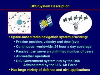
GPS Enhanced PFD System Software Presentation. Eric Grossmann. Presentation Summary . General System Specifications. Timeslice Kernel Tasks. Modules. Data Flow Diagram. Individual Task Descriptions. CPU Load. General System Specifications. MCU PSOC 1 CY8C24794

E N D
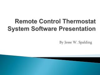
GPS Enhanced PFD System Software Presentation Eric Grossmann
Presentation Summary General System Specifications Timeslice Kernel Tasks Modules Data Flow Diagram Individual Task Descriptions CPU Load
General System Specifications • MCU PSOC 1 CY8C24794 • 4 Digital Blocks & 6 Analog Blocks • Bus Frequency: 24 MHz • Timeslice Kernel • Timeslice Period:100 ms • Memory Available: • 16k Flash • 1k RAM • Memory Requirement: • Less than 1k Flash • 1k RAM
Timeslice Kernel Tasks • Startup Task • Acceleration Detect Task • Immersion Detect Task • Switch Detect Task • GPS Rx Task • Tx Task
Startup Task • Initializes the system • Execution Time: • 100ms worst case. • Period: • Once at Startup
Acceleration Detect Task • Observes hex output from the sensor • Passes a hex output to the MCU. • Period 100ms • Execution Time 5μs
Immersion Detect Task • Observes changing voltage from the sensor • Converts the voltage into digital format • Passes voltage level as a hex output to the MCU. • Period 100ms • Execution Time 5μs
Switch Detect Task • Waits and recognizes a voltage level on a toggle switch. De-bounces the switch. • Period: 1s • Execution Time: 10μs
GPS Rx Task • Observes hex output from the sensor • Passes a hex output to the MCU. • Period 300s (sporadic) • Execution Time 5μs
Tx Task • Observes hex output from the MCU • Passes a hex output to the Transmitter module. • Period 300ms (sporadic) • Execution Time 5μs
CPU Load • Max CPU Load • 5us/100ms + 5us/100ms + 10us/1000ms + 5us/300000ms + 5us/300000ms = 0.01% CPU Load
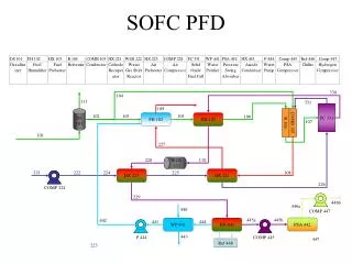
Data Flow Diagram ------------------------------------------------------------ Hardware GPSPFD.c