Download

1 / 18
260 likes | 799 Views
ABEM Terrameter LS. Field-proven Imaging system measuring Resistivity, time-domain IP and SP. Designed for high reliability and robustness under harsh field conditions. Highest productivity using ABEM unique roll-along method. Surveying principle for multi-electrode systems. cable 1.

E N D
ABEM Terrameter LS Field-proven Imaging system measuring Resistivity, time-domain IP and SP.
Designed for high reliability and robustness under harsh field conditions.
Highest productivity usingABEM unique roll-along method.
Surveying principle for multi-electrode systems cable 1 cable 2 cable 3 cable 4 T T T T T T T T T T T T T T T T T T T T T T T T T T T T + + + + + + + + + + + + + + + + + + + + + + + + + + + + + + + + + + + + + + + + + + + + + + + + 4 cables for an efficient roll-along survey!
Easy to use with multi-lingual graphical user interface on sunlight readable color LCD. Integrated workflow guidance
Open communication platform for data exchange, internet connectivity and remote diagnostics (TCP/IP, USB).
System diagnostics and fault tolerance. • Built-in self-test of inputs and transmitter. • Transmitter load, temperature, power disapation, power supply voltage monitoring • Automatic monitoring of all relay switch operations. • Relay coil current monitoring.
Superior quality in data acquisition with powerful transmitter and high dynamic range multi-channel receiver.
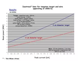
Transmitter • True constant current transmitter • 250 W output power • 600 V max output voltage • 2.5 A max output current • Full waveform monitoring of output current and voltage
Transmitter working ranges Voltage Current
Receiver • 4 or 12 input channels • Galvanically isolated inputs • Arbitrary No. of IP time windows • Full waveform sampling and recording(up to 30k sample/s). • 24 bit A/D converters • Auto-range ±5V or ±600V
The advantage ofgalvanically isolated Inputs • Superior common mode range (2 kV). • Eliminates over-range measuring errors.
Electrode switch • Full 10x64 matrix relay switch. • Efficient 12 channel switching. • 64 electrodes simultaneous switch capacity (=> 81 electrodes with standard cables).