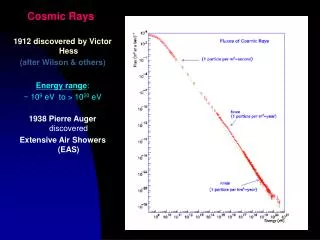
Download
1 / 36
370 likes | 505 Views
Drift Tube Calibration and synchronization and Cosmic rays data. I report on - the parameters that define the performance of the DT chambers and of their trigger capability - the way we may extract them assuming we have the drift time and the trigger information. and on

E N D
Drift Tube Calibration and synchronization and Cosmic rays data I report on - the parameters that define the performance of the DT chambers and of their trigger capability - the way we may extract them assuming we have the drift time and the trigger information. and on - preliminary results from cosmic rays data on DT with autotrigger slides 23-29 Preliminary Muon PRS workshop @Torino A.Meneguzzo-Padova
DT Calibration and synchronization : outline • I first introduce the calibration parameters for • the • Chambers. Chamberperformance is defined by noise, dead channels , efficiency , drift time/positionlinearity, • Local Trigger. LT performanceis defined byefficiency , purity, bx assignment andlocal track parameter ( phi and phib) accuracy, • Track reconstruction. Reconstruction performance (HLT and offline) is defined by muon pt resolution in standalone , barrel -tracker extrapolation efficiency, global muon pt resolution. • and after the way we can determine • them • using during commissioning, magnet test and LHC startup Random triggers , TP signals , tracks (cosmic rays and pp tracks) Muon PRS workshop @Torino A.Meneguzzo-Padova
* * * * * * * L 3 points track * * * H4 points track * * * * * * * * * H N H L BTI outer * * * * * * * TRACO TSS/TSM Hi HH HL (LH) Ho BTI inner * N H H H * * * DT Local Trigger parameters : introduction Let a DT chamber in a space with a B(x,y,z) magnetic field, working in standard conditions, and a track with its time and direction passing the chamber in a zone where its ionization charges reach the wire with a mean drift velocity vd, The performance of the Local Trigger depends essentially on two of the parameters which must be set : 1) the parameter ST i.e the meandrift velocity set in each BTI of the minicrateand its relation to the mean drift velocity Vdrift of the chamber [~ ST *12.5 = d /Vdrift ns = Tmax ; ST=distance of staggered wires in units of BTI frequency clock(80MHz)]. Granularity of ST is 1/2 i.e. Dtmax=6.25 ns = Tmax*1.6 % ] 2) The relative phase of the timeof the track with respect to the clock in the Mini Crate [ the alignement is sampled at the clock frequency and its efficiency depends on the phase of the clock of the Mini Crate with respect to the time of the track in the chamber]. 3) Geometrical parameters that define the relative correlation between BTIs in the 2 PHI SLs . Muon PRS workshop @Torino A.Meneguzzo-Padova
What do we know about the dependence of the efficiency Vdrift(ST parameter ) in the Local Trigger ? From Data ( see slice # 30): TB 2003CMS in 2004/045 Local Trigger efficiency does not change for Vdrift error of ~1.7% TB 2000(only BTI trigger i.e. trigger only from one SL )[CMS NOTE 2001/052 ,NIM 1999] Vdrift systematic error ~8 % with track angle 00 : BTI H triggerefficiency =~80 % as expected with no error for 200 tracks , BTI H triggerefficiencydrops at 68% (80% expected with no error) for 350 tracks BTI H triggerefficiencydrops at 30%(75 % expected with no error) From EMULATOR : The behavior ofTB 2000 confirmed with old EMULATOR(zotto &CMS note 2001/052) The behaviorof TB2003 confirmed with new EMULATOR (Vanini talk and CMS in p) Full dependence can be studied for any wanted Vdrift error. CONCLUSION: 1.7% accuracy is good enough on Vdrift parameter for the efficiency of the LT Muon PRS workshop @Torino A.Meneguzzo-Padova
Dependence of mean drift velocity as a function of magnetic field Dependence of mean drift velocity as a function of angle vdrift dependence in the DT cell Drift velocity is constant in the Ar/CO2 gas mixture 85/15 at the nominal HV cell setting. The apparent drift velocity varies only due to Lorenz angle in presence of B field normal to the wire and with the angle of incidence of the track. The dependence of the drift velocity on angle and B field has been measured[TB2000 CMS NOTE 2001/041] and computed with Garfield cell simulation [Bologna CMS NOTE 99/064 and Madrid CMS note in preparation] . The simulation results have been verified with the measured ones. At trigger level we cant correct for the angle phi but for high pt tracks it is well within ~400, neither for the magnet field but the expected B field should be below 0.3 T everywhere except only in MB1 stations in the wheel #+2 and #-2 where it may be of some relevance(up to .8 T). Muon PRS workshop @Torino A.Meneguzzo-Padova
Synchronization There are two Synchronizations processa) inside each chamber (sampling phase) b) between each chamber and the Sector Collector (transmission phase) M. Dalla Valle talk , HH efficiency in a given chamber as a function of phase. For tracks completely out of sampling_phase, the local trigger is output in two contiguous bx and the trigger quality is deteriorated. Muon PRS workshop @Torino A.Meneguzzo-Padova
Dependence of Trigger efficiencyLocal Trigger Phase(Sampling Phase) From TB 2001 data: CMS NOTE 2001/51 Single SL data : depending on the phase of the sampling clock the Htrig efficiency ranges from 70% to 80%. From TB 2003 data: CMS IN 2004/045 For Configuration HH+HL+LLin the Traco, the Local Trigger efficiency varies from 90% to 65% for any phase From EMULATOR : TB 2003 and 2001 behavior confirmed with EMULATOR . TB 2003 and 2001 behavior confirmed with EMULATOR . Full dependence can be studied for any wanted error. Muon PRS workshop @Torino A.Meneguzzo-Padova
How best Sampling_phase for bunched particles can be measured. The procedure exists ( coded) , has been tested with TB Data 2003 (CMS IN 2004/042) and with TB2004 for 2 chambers. The algorithm is luminosity independent .It is based on the fact that for in phase tracks the output of correlated triggers is always in the same bx , for out of phase events is in two bx. The Mean Time RMS distribution & / or the HL/HH trigger quality ratio as function of phase are used. HH+HL+LL Trigger efficiency as a function of phase efficiency vs sampling phase HL/HH MT RMS Track- clolck phase (arbitrary offset ) TTCrx delay ns Muon PRS workshop @Torino A.Meneguzzo-Padova
Remarks on vdriftandon sampling_phasesetting in the Local Trigger a)The Local Trigger drift velocity (ST parameter) could be set individually in each BTI but drift velocityand sampling_phase of the Local Trigger are correlated and there is only 1 sampling phase value for each Mini Crate i.e. for each DT chamber so just one setting per chamber for the phi SL is reasonable. Different values of vdrift on Theta SL BTIs can be set since in theta the angle of track is fix but compromise with sampling_phase have to be found. b)The apparent mean drift velocity in the CMS DT chambers at LHC can be measured or can be computed from simulation. The range of variation inside a chamber is anyway ~2% due to track angle (TN 2001/041 , TN 2003/052) and that can be correct for only on HLT and offline. The same for the error in MB1/+-2 due to the B field. c) The signal propagation along the wire produces an intrinsic phase error which ranges from 0 up 4.5 ns/meter of wire length (TN 2003/042)[9ns for phi wires and 14 ns for theta MB3 wires]. d) The intrinsic phase error for cosmic rays on just one chamber ranges from 0 to 25 ns. Muon PRS workshop @Torino A.Meneguzzo-Padova
How do we check the value of the mean drift velocitywith bunched particles (i.e. all events with ~ the same phase ) • from track fit minimization with vdrift as free parameterCMS NOTE 2001/041,CMS NOTE 2003/001,etc • from Mean Time & Time box (slide #31) • Commissioning and magnet test will be performed with cosmic rays. • Can we measure the Drift Velocitywith autotriggered data on cosmic rays? with which accuracy ? • From tests on cosmic rays and autotrigger performed in Legnaro even if the T0 ( necessary for a good drift velocity measurement) varies event by event from 0 up to 25ns, there are hints that , with some easy(?) software implementation, a T0 and so Tmax and vdrift accuracy of 3% at least can be set . • Can we autotrigger on cosmic rays ? With which purity ? • ( see second part of the talk, COSMIC RAYS with AUTOTRIGGER slides 23-29) Muon PRS workshop @Torino A.Meneguzzo-Padova
Commissioning verify DT chamber performance and working point ( minimum noise, max efficiency , best drift time linearity and resolution) the parameters are : HV and Threshold Operations at commissioning step 0- with TP signals, FE channels and Mini Crate connections are checked ( DCS local DAQ …) step 1- with random triggers (L1A) the noise is measured as a function of HV and of Threshold up to values a little above the working voltage ( DCS local DAQ…). step 2- The efficiency of one SL as a function of HV and Threshold can be checked - setting the others SLs at nominal HV and Th, - Trigger : L1A from the autotrigger type H of the chamber (*) (BTI SL under test masked. Only H trigger on the other SLs. Best configuration ?? ) Muon PRS workshop @Torino A.Meneguzzo-Padova
Operations at commissioning continue - scan in HV and Threshold in the SLi(*) - Results from TDC data : occupancy in time window * , timebox shape *, Mean Time shape *, ( DCS local DAQ…), - from track reconstructioncell resolution ,Drift Time / position linearity * and efficiency * (?) - with standard configuration on all BTIs, check trigger efficiency of the Sli from the ratio of HL/HH trigger quality -Quasi automatic algorithm must be implemented *? NB: is necessary a quasi automatic HV scan procedure and analysis * semi automatic analysis programs have been already prepared and used in the on line program * semi automatic analysis programs not ready (*) trigger operation not done yet , must bedefined in Legnaro and at ISR Muon PRS workshop @Torino A.Meneguzzo-Padova
What do we know of Single SL Local Trigger : The BTI H trigger efficiency is 80% with less then 5% wrong bx assignment. NIM A 438(1999) 302 and CMS NOTE 2001/051 Standard acceptance Minimal acceptance Muon PRS workshop @Torino A.Meneguzzo-Padova
For HV & Thresholdefficiency curve we may use the • occupancy in time window • Track reconstruction efficiency ( even with large error 12*55mm~600mm/hit • Drift velocity can be measured at 3 % (software to be implemented) and • x(t,B=0,angle) parameterization can be verified • Work to be done before commissioning : • test the 1 SL autotrigger capability and define the best trigger configuration for that • (people ? , hardware ?, software implementation ? in Legnaro and at ISR) • define a standard sequence with DCS and DAQ and define quality cuts for commissioning likes production cuts Muon PRS workshop @Torino A.Meneguzzo-Padova
Synchronization in the cosmic challenge and magnet tests • GOALS ( as far as I understood but see Benvenuti talk): • Cabling and signal distribution checks • Study the cell performance with the real B field • - Learn how to synchronize a sector as in TB2004 but without external scintillators. Particles are not bunched so the synchronization process is not between the particle generation ( 40MHz clock) and each chamber but between different chambers ( see E. Conti and Dalla Valle talks). Muon PRS workshop @Torino A.Meneguzzo-Padova
Synchronization in cosmic challenge and Magnet test Sequence of operation: a) with TP -Check all cabling compatibility and TTC signal distribution timing with TP signals generated in the 4 Minicrates of the sector on a common LDAQ signal. -Choose the trasmission_phasein order to have 100% trasmission efficiency from the LT in the chambers to the Sector Collector. ( How ? ) . b) Set each chamber at the HV and Th working point defined at commissioning . c) Chose 1 chamber for HH+HL autotrigger and set SC so that it picks the autotrigger signal of the chosen chamber and sends it back as L1A to all chambers of the sector. d) Find in each chamber the sampling_phase for local synchronization to the triggered events in the other chambers with SC L1A (see E.Conti). e) Take data with magnetic field with SC L1A or DTTF L1A (see E.Conti). Muon PRS workshop @Torino A.Meneguzzo-Padova
bx 102 in MB3 bx 103 in MB3 bx102 in MB1 bx 101 in MB1 cosmic time ns How can wesynchronize two or more chambers in the cosmic test : example The color gives the bx of the autotrigger in each chamber for a given time of the cosmic ; the y axis gives the efficiency that any cosmic produce a autotrigger (HH or HL or LL) in that chamber passing at a the time set in the x axis. In the example , lets a cosmic at t=12 ns. The probability that chamber MB3 has a autotrigger is 90% , and the trigger output is at bx # 102 with ~100% probability. The same cosmic in MB1 has a probability of 70% to trigger and half a probability to be in bx #101 and half at bx #102. Setting in phase the chamber MB1 with respect MB3 means to move the TTCrx delay ( in the example of 12 ns ) so each chamber gives the same bx bx 103 in MB1 Muon PRS workshop @Torino A.Meneguzzo-Padova
TB2000 Dependence of mean drift velocity as a function of BN ~ Dv/v= 6 % Dependence of mean drift velocity as a function of magnetic field in the expected range Expected BN in the first layer of MB1 stations in sector #4 for the 3 wheels. TB 2000 Dependence of 1 SL H trigger efficiency as a function of magnetic field Can we measure the drift velocity in the magnet test and check the cell and the trigger behavior ? Yes but with a accuracy do to T0 jitter of 3% ; better if event by event T0 corrections possible wheel +2 wheel +1 wheel 0 Muon PRS workshop @Torino A.Meneguzzo-Padova
LHC startup • Operations at startup : chambers already set at nominal HV and Threshold as from magnet and cosmic tests; Local Trigger configuration 0 loaded. The sampling_phase is set as a function of meanTOF in the chamber with respect to TP syncrhonization. • Step 1-in technical runs with random triggers (L1A) the noise is measured ( ? as a function of HV and of Threshold up to the working voltage? DCS local DAQ operation). • Step 2 - data are collected locally in autotrigger chamber by chamber , • from timebox and MT verify bx assignment and Drift velocity, • Measure/verify sampling phase and adjust TTCrx fine delay in each chamber (TOF+phase), • adjust trasmission of any chamber to the SC , • DT LT information sent to DTTF for DTTF synchronization. After step 1 we can start to be read out and to sent LT segments at least with ~70% efficiency for correlated ones. In the worst situation, being completely out of phase, the good output trigger of each chambers may be in 2 contiguous bx with 65% efficiency. The probability to send at the same bx the 2 LT of 2 completely out of phase chambers is so ~24 % but in a sector there are 6 possible combination of 2 chambers. So we should trigger with some reasonable efficiency. From analysis of Drift Time data (MT in the LDAQ) we can find if the bx assignment was wrong of +1 or -1 bx with respect an expected one . The fine phase can be adjusted locally and the coarse phase in different chambers of this doublet can be checked and adjusted at SC or at SC level. With a iterative process all chamber of a sector can be syncrhonized Muon PRS workshop @Torino A.Meneguzzo-Padova
Conclusion : DT CALIBRATION AND SYNCHRONIZATION at LHC LOCAL TRIGGER CALIBRATION : we want to verify the Drift Velocity i.e. to measure the mean drift velocity in each chamber from drift time data (slide#31). A sample of ~10000 events/chamber is a good starting statistic ; the measure can be performed locally, at LDAQ or/and at the HLT farms level, the vdrift corrections with respect the nominal values is expected to be ~ 1.6% which is also the granularity on the hardware. Local trigger SYNCHRONIZATION : we have to find the best phase of the considered tracks with respect to the sampling clock. The best phase is TOF dependent so it must be performed with pp tracks. The best phase is vdrift parameter dependent and so few values of vdrift parameter should be checked. ~5000-10000 events /phase/chamber are enough with 25 steps in phase of 1 ns. The measure can be done locally in the LDAQ or/and at the HLT farms level .How can we trigger in order to have data for checking Vdrift and for synchronization?Even if chambers are not synchronized , LT efficiency is above 65 % for any phase value.Once chambers are locally synchronized , SC synchronization and DTTF synchronization can be easily performed as in TB2004 (Marcellini talk). fullL1 efficiency:what is the impact of no calibration in the LT ? We do not have data but in HLT code LT is perfectly simulated. In HLT there is a perfect LT synchronization ( mean TOF in a chamber set to 0 ) but all drift time errors are included (cell non linearity, wire propagation, TOF differences) and there is just one LT Vdrift parameter for all chambers so HLT L1 simulated results (A.Vanini and S.Lacaprara talks) refer at a perfect synchronization but at a minimum calibration. Muon PRS workshop @Torino A.Meneguzzo-Padova
Conclusion : DT CALIBRATION AND SYNCHRONIZATION In HLT and OFFLINEcode , once a rough track angle and position is computed in both projections, the T0 incertitude for the propagation along the wire is corrected for, the B field and the position in the cell and the angle are known and so x can be computed from x=x(t,B,angle) parameterization. That is what is done in the current reconstruction code of the simulated data. Offline calibration is so to compute-the relative difference in time between the channels of a chamber (with TP data , done already at commissioning. The measured differences are of the order of 1ns in all fully equipped chambers as expected from cabling accuracy), -the T0 of each chamber (from residuals and/or from time box and MT) and verify that -the parameterization is correct from residuals and from t = t (x) relation. The other aspect is -alignment (see Matorras ) between chambers. For LHC this can be performed with alignment data and with well locally reconstructed pp tracks . -B field map accuracy.The worst situation for no calibration in offline – other then B field and alignment- can be a local DT reconstruction without parameterization, with a uniform constant vdrift velocity and T0 in each chamber, vdrift velocity and T0 computed chamber by chamber directly from data (that is what is done in the cosmic data reconstruction ). One could have events with global L1A shifted of 1 bx depending of the kind of trigger (muon RPC, muon CSC, Muon DT , Ecal, Hcal and in each one could have a sector or wheel dependence). That is local (DTTF from sector to sector for DT) and global trigger synchronization that can be performed only checking the data (timebox and MT)as a function of the different trigger origin. Muon PRS workshop @Torino A.Meneguzzo-Padova
CONCLUSION : DT Calibration and synchronization the parameters areHV and Threshold defined at commissioning but verification in B field and at startup neededsee commissioning slide.11 Chamber Local Trigger: the parameters aredrift velocity(1/Chamber but no strong variation expectedif a fix value in all detector is used) andsampling_phase (1/Chamber must be measured with data ) see LT introduction slide 4 HLT and offline (consideration only for DT)the parameters are T0(1/Chamber), x= x( tdrift ,B, angle) parameterization or vdrift(angle,B) and geometry alignments. The channel by channel T0 variation is very little by construction i.e. ~1 ns, is constant in time and is measured with TP. see Amapane Lacaprara Matorras talks and CMS notes • WORK to DO : • - Verify completeness of calibration and synchronization analysis and of foreseen processes. • Prepare semiautomatic procedure interacting with trigger , DCS and DAQ people. • Test procedure. Muon PRS workshop @Torino A.Meneguzzo-Padova
cosmic track DAQ MB3 CH2 Mini Crate MB3 CH2 Autotrigg CH2 L1A MB3 CH1 Mini Crate MB3 CH1 Autotrigg CH1 g Trig Scint 5 Scint 5 Signals in input to CH1 TDC channels for monitoring Cosmic rays autotriggered by a MB3 chamber in Legnaro.CMS in 04/045 Cosmic rays set up LNL : MB3 chambers BTI and TRACO set quiet configuration, the so called sync388 set-up i.e. only very high quality trigger in the TRACO: HH, HL or a H certified by a H_trigger in the theta view. Autotrigger SELECTION only H in CH2 Trigger : autotrigger L1A of the Mini Crate Muon PRS workshop @Torino A.Meneguzzo-Padova
Cosmic ray autotrigger with 1 chamber , With autotrigger, the gitter of the cosmic time with respect to the L1A trigger was verified from the time of the scintillator recorded with respect to the autotrigger. The time of the scintillators signals recorded with respect to the autotrigger are 90% within 25 ns Muon PRS workshop @Torino A.Meneguzzo-Padova
Cosmic ray autotrigger with 1 chamber Autotriggers Cosmic rays have flat distribution in time but L1A stops the TDC always in phase with the eadge of the clock : any event has an error do to the clock of about 25ns/(sqrt 12). The range of the offset can be seen on the Mean Time plot. Tmax distribution ~flat in ~50 ns ( 64 tdc units). But the offset is the same in all the drift times recorded , event by event From the correlation a 3% accuracy on Tmax should be reachable (15ns/500ns ) , correcting To_ev event by event from the plot above . Or with a minimization fit ( event by event) of all the residuals of the reconstructed tracks segments with To_ev as parameter, Muon PRS workshop @Torino A.Meneguzzo-Padova 1 TDC count =0.78 ns
Cosmic ray : autotrigger with chamber CH2 Autotrigger purity. Reconstructing offline the track segment of the triggering chamber with the standard Orca package (with no T0 correction event by event), in 99% of the events a track in both projections has been found ; in 0.5 % of the total events the chambers had many hits ( cosmic shower ). The expected single point error is around 500 mm as it should with a 12 ns time error. MB3 #36 no alignments corrections fit performed : - in q with 3 or 4 layers -in j with at least 3 and up to 8 layers angle distribution of the tracks reconstructed in the event Residual 7 point fit 400 mm error layer 1 450 mm j layer 7 550 mm q Muon PRS workshop @Torino A.Meneguzzo-Padova
Cosmic ray : autotrigger with 1 chamber, drift time data and autotrigger signal from chamber1 and chamber 2 Track segment Reconstruction with standard Orca package (with no T0 correction event by event) : 99% efficiency on the triggering chamber. In the other chamber , due only to geometrical reason .( taking in account the cell disconnected ) the track reconstruction efficiency is arounf 96%. NB the T0 of the two chambers are shifted of ~12ns : the shift cannot due to TOF (not more than 2 ns). It is due essentially to a the phase of the sampling clock in each chamber with respect to the muon., >> Tbox of the 2 chambers Occupacy in the 2 chambers Residuals of the Position of the track Reconstructed in ch1 extrapolated to ch2 xch2-xch1extrapolated cm Muon PRS workshop @Torino A.Meneguzzo-Padova
Relative autotrigger output time of the 2 chambers 50000 ev The recorded autotrigger signal of CH2, the autotriggering chamber, is a spike and 100% efficient. In 3 % of the events there was a double autotrigger but in the 5ms window of tdc, compatible with the cosmic rate ( ~2K Hz). TDC units Time The recorded autotrigger signal of CH1 presents instead two spikes 25 ns apart (32 tdc units) , is ~68 % efficient and the shift in time with respect to the CH2 autotrigger signal is 10 ns ( the two autotriggers are recorded in 2 channels of the same TDC). That agrees with the 12 ns shift of the time boxes and 2 ns of TOF . The clock of CH1 is displaced of 10 ns with respect to the clock of CH2 so it is completely out of phase for the muons recorded by the CH1 chamber. The experimental results agrees completely. 50000 ev TDC units Time Muon PRS workshop @Torino A.Meneguzzo-Padova
Conclusions : cosmic rays data studies with DT autotrigger • The test performed in Legnaro with the autotrigger signal as L1A, shows that with cosmic rays the Mini Crate can work and data give plain information as far as uniformity is concerned • on the chamber performance • on the trigger performance • and • on the role of phase in different chambers. BACK UP SLIDES >>>>> Muon PRS workshop @Torino A.Meneguzzo-Padova
CMS NOTE 2004/045 TB2003 bunched beam : Local Trigger HH+HL+LL Local Trigger efficiency (vs phase) for 2 different vdrift in the BTI and 2 track angles CMS NOTE 2001/052 TB2000 Only 1 SL BTI and emulator H efficiency (within 6 ns window phase) for different vdrift in the BTI vs track angle 0.9 Vdrift=50mm/s. Vdrift=55.1mm/s 0.6 Angle with respect to normal to the chamber degrees NB: The efficiency for tracks normal to the chamber does not depend strongly on the assigned drift velocity if the error is within 8%. It is relevant as soon as the tracks hits cells not in the same column. Muon PRS workshop @Torino A.Meneguzzo-Padova
How do we check the value of the mean drift velocity [in external scintillator bunched cosmics or with bunched particles: all events with ~ the same T0 ]? • with track fit with vdrift as free parameterCMS NOTE 2001/041,CMS NOTE 2003/001,etc • from Mean Time & Time box T4 Tmax =(T4 +2T3 + T2)/ 2with T2,3,4= t (tdc)234-T0 T3 T2 Vdrift = d / Tmax T1 d staggering=21mm Tmax T0 From the MeanTime we measure Tmax and so the drift velocity T0 of the drift time is measured from the Tbox; it depends on TOF , cables etc etc Muon PRS workshop @Torino A.Meneguzzo-Padova
END BACK UP SLIDES >>>>> Muon PRS workshop @Torino A.Meneguzzo-Padova
configuration 1 LHP pp : Local Trigger configuration 1 loaded Local Trigger configuration 0 loaded configuration 2 0 Commissioning Magnet Test & LHC 1 Data ( DTand LT) 0 Data ( Drift Time and LT) x,y, z ,B & angles from (CMSIM) OSCARsimulation hits in the specific cell+TB -Measure Vdrift and phase - update configuration ST & and Phase a) -Measure Vdrift and phase - update configuration ST & and Phase Drift time from parametrisation: t=F( xloc,yloc, zloc, B, philoc,thetaloc) [ see Amapane talk) and Bologna &Madrid drift time cell simulation (Garfield ) and parametrization] Calibration scheme (….. For discussion…) b) 3 Emulate the Local Trigger performance as a function of the ST parameter and phase ( see Vanini talk) ; vary the ST and phase parameter and find the best value 1 c) has been done at TB and with cosmic ray and can be always used during data taking ; standard procedures under study The algorithms is used in the HLT simulation. Tuning has been done partially (see Vanini talk ) on TB and cosmic ray (point c). Can be used on data offline. Muon PRS workshop @Torino A.Meneguzzo-Padova
TP signals : flow of command with TP ( In the plotTP is generated within 0 ns between staggered cell i.e emulates normal tracks in the middle of a semicell ) TP_go or Orbit signl L1A signal SC/Global Clock in CH1 TP in CH1 TDC fine countsin CH1 TDC windowin CH1 L1A signal inside CH1 LT trigger cotputby CH1, bx =i Clock in CH2 TP in CH2 TDC fine countsin CH2 TDC windowin CH2 L1A signal inside CH2 ~Tmax/2 LT trigger cotputby CH2, bx =i Muon PRS workshop @Torino A.Meneguzzo-Padova
Introduction to DT Local Triggr parameters Glossary Configuration : it contains the parameters for the Read Out and for the Local Trigger (masks, triggers parameters and requirements) , see Marina Passaseo talk. Autotrigger : signal that is generated under specific requirement on the Local Trigger quality of a chamber. It can be used for the L1A generation only locally or used by the Sector Collector that receives the track segments from 4(5) chambers to generate the L1A for all the chambers of the sector. (see Dalla Valle talk). Nominal HV & Nominal Threshold are the working point of the chamber defined at TB & at ISR Standard configuration : the configuration foreseen for normal condition LHC Muon PRS workshop @Torino A.Meneguzzo-Padova