Download
1 / 29
290 likes | 398 Views
Calorimeter Electronics. Jim Pilcher 11-Dec-2008. Introduction. Calorimeters essential for energy measurement in particle physics Detection over a wide range of energies Incident particles deposit their energy in a medium

E N D
Calorimeter Electronics Jim Pilcher 11-Dec-2008
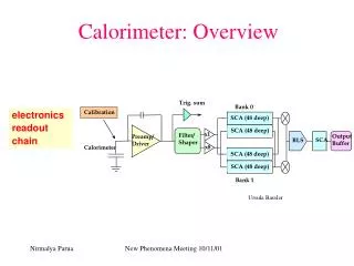
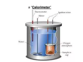
Introduction • Calorimeters essential for energy measurement in particle physics • Detection over a wide range of energies • Incident particles deposit their energy in a medium • Tank of liquid (water or scintillator), dense medium(iron/scintillator), air • Can be very large (esp. for neutrinos and cosmic rays) • In many calorimeters optical EM radiation is produced • Electronics converts this signal to digital information • For signal processing to calculate energy, time, quality of the measurement J. Pilcher
Introduction • SNO Calorimeter • Detect Cerenkov radiation from interactions of ~ 106 eV neutrinos • Also calorimeters in Double Chooz, Daya Bay, Minos, MiniBoone J. Pilcher
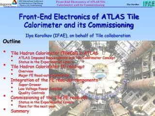
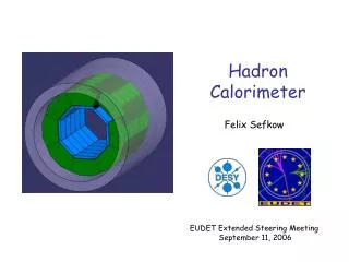
Tile barrel LAr hadronic end-cap (HEC) Tile extended barrel LAr EM end-cap (EMEC) LAr EM barrel LAr forward calorimeter (FCAL) Introduction • Collider detectors calorimeters (to E ~ 1013 eV) • Example for ATLAS Calorimeters • But also ALICE, CMS, LHCb, CDF, D0 • Will not discuss noble liquid calorimeters today J. Pilcher
Introduction • Auger observatory (to E ~ 1021 ev) • Detect fluorescence radiation from air showers induced by cosmic rays • Calorimeter absorption medium is the earth’s atmosphere • Detect muons from decay of hadrons produced in these air showers J. Pilcher
Photo-detectors • Role is to convert optical photons to electrical signal • Photons from Cerenkov radiation or scintillation • Amplify the number of electrons if possible • Many types • See proceedings from Beaune Conference 2005 in NIMA 567 (2006) • In this talk I touch on a few important types • Photomultipliers, Hybrid Photo Diode (HPD), Silicon PMT(SiPMT) • Choice depends on necessary area coverage, spatial segmentation, operation in magnetic field J. Pilcher
Photomultiplier Tubes (PMTs) • As used in ATLAS hadron calorimeter • Ideal current source • Operated at gain of 105 J. Pilcher
Photomultiplier Tubes (PMTs) • Very diverse device • Many sizes and shapes • Much experience from years of usage and development • Wide range of gains (~ 104 to ~107) • Set by operating voltage and number of amplifying stages • The ATLAS device is 10-year-old design • Now quantum efficiencies over 40% • Segmented anodes (eg. 8x8) J. Pilcher
The Physics of PMTs • Design principle • Amplification by electron acceleration in electric field and secondary emission from a metallic dynode Gain = V V is operating voltage is ~ number of stages Fast devices signal rise time ~1ns transit time ~10ns J. Pilcher
Issues to consider for PMTs • Gain stability • Depends on geometry of dynodes • Emission coefficients of photocathode and dynodes • Requires careful control of temperature and HV • ATLAS PMT have G/G ~ 0.2% / C 1% / V • Magnetic field sensitivity • Low energy secondary electrons are easily deflected • Must use magnetic shielding in magnetic fields • Even for earth’s field • ATLAS PMTs shielded for axial B ~ 200 G (for 1% variation) • After-pulsing • Electron interaction with residual gas in tube • Secondary signal correlated in time with primary J. Pilcher
Hybrid Photodiodes • Used for CMS hadron calorimeter • Must operate in strong magnetic fields • CMS HCAL designed for ambient field of 4T • Need for segmented anode • Limited operational experience with large systems of HPDs J. Pilcher
Photons Electrical signals The Physics of HPDs • Incident photons produce electrons in photocathode • Electrons accelerated in electric field (few kV) • Energetic electrons are strike the silicon • Produce hole-electron pairs and hence current in reversed biased diode (gain) • CMS device operates at 12 kV for gain of 2500 • Can segment silicon structure for spatial information J. Pilcher
Issues to consider for HPDs • Must operate at high voltage without sparking • Cross talk can occur between readout pixels • Sensitivity to variations in magnetic field direction • modifies electron trajectories J. Pilcher
Silicon Photomultipliers • Development to useful devices in recent years • Just emerging from R&D stage • Pixels of ~ 30 m ~ 30 m formed on a common silicon substrate • Typical sensitive area 1 mm 1 mm • ~ 1000 photosensitive pixels J. Pilcher
Physics of Silicon Photomultipliers • Photons produce hole-electron pairs in Si • Quantum efficiency > 70% • Applied voltage of ~ 50 V produces high local electric fields because of tiny size of structure • Results in gains of 106 • A saturated Geiger mode response (digital) for each pixel struck by photon • Signal from all pixels is on a common output terminal Can count number of photons detected from size of signal J. Pilcher
Issues for Silicon Photomultipliers • Sensitive area is small • Could use one per fiber • Photon detection efficiency ~ 50% because of geometric filling efficiency of pixels • Dark count rate is high ~ 300 kHz • Still limited experience in large systems • CALICE calorimeter for linear collider R&D uses them J. Pilcher
Pulse Shaping • Signal from photodetector is often conditioned prior to digitization • In some applications the photodector signal is digitized at very high rate (Gsps) to record the “wave form” as in an oscilloscope • I will not discuss this option here • Make pulse shape insensitive to timing variations in light collection • Fine details of waveform from photodetector may not be necessary for measurement of interest • Standardized shape facilitates time measurement • Can take multiple samples of the signal to allow estimate of time • Energy and time measurement can be made with the same hardware • Sub nanosecond time measurements are possible • Digital signal processing • Match bandwidth of PMT signal to bandwidth of ADC • Higher speed ADC increases power and cost • 10-year-old ATLAS design was close to practical limit at the time • Higher speed now practical if needed (eg sLHC readout) J. Pilcher
Pulse Shaping • ATLAS example • Very similar solution in Auger front-end electronics and E14 experiment at J-PARK • Shaper integrates input pulse and produces standardized shape determined by electronics components • Output pulse area proportional to charge of input pulse • If output shape is invariant then its amplitude is proportional to input charge • Can make a very linear system J. Pilcher
ATLAS TileCal Pulse Shaping • Photomultiplier is a near-ideal current source • Current is very insensitive to impedance load on anode • This allows a shaper built with fully passive elements (LC filter) • Very low noise since no active components and very low resistance • TileCal shaper is a 7-pole Bessel filter • Can produce near-Gaussian output shape for digital sampling J. Pilcher
ATLAS TileCal Pulse Shaping • The circuit • Followed by buffer amplifiers to set gain and limit maximum signal • Use two gain ranges for increased dynamic range J. Pilcher
Pulse Shaping • Issues slightly different in the noble liquid calorimeter Denis will describe • Tradeoff between long shaping time for low electronic noise and short shaping for low noise from multiple interactions within time window J. Pilcher
Digitization • Can follow shaper with sampling ADC • For multiple samples of the shaped waveform • Extract, energy, time, quality factor for pulse shape • Intense commercial development of ADCs for high volume applications • Medical instrumentation, cellular phone systems • Maxim, Analog Devices, Linear Technology, Texas Instruments • Dramatic improvements in performance with time • Smaller feature size • Less power • Higher speed • Lower cost • Sampling rate may be determined by application • At LHC sample at 40 MHz bunch crossing rate • Required dynamic range may necessitate multiple gain scales J. Pilcher
Digitization • Now lots of choice for ADC • e.g. Maxim offers 28 12-bit ADCs capable of sampling at 40 Msps or greater • Similar for other manufacturers • Let’s examine relevant characteristics • Example, MAX1126 (4 ADCs in one package) J. Pilcher
Digitization • Tiny device • Difficult to probe with scope • Optimized PCB design is essential to realize its performance • Generally pipelined, multistage ADCs • Sample every clock cycle • Deliver digital output 7 cycles later • 7 internal ADCs working in parallel J. Pilcher
Digitization Pipeline J. Pilcher
ADC Limitations • These are NOT ideal devices • Might expect resolution of step size / sqrt(12) if all steps uniform • Step sizes NOT uniform • Differential non-linearity • This is a very well behaved design J. Pilcher
ADC Limitations • Also, deviations of response from straight line fit • Integral non-linearity This is a very well behaved design Should not rely on averaging ADC measurements to an accuracy better than 1 count J. Pilcher
Data Flow • ADCs produces 2 x 12 bits (if dual range system) every 40 MHz • 960 Mbps • Essential to filter this to extract signal of interest • May require fast digital link to transport data to digital signal processor • A major challenge • Systems may have 1000’s of channels J. Pilcher
Conclusions • Modern readout electronics capable of high dynamic range measurements • Dual range system can give 16-bit dynamic range • Can measure timing with same hardware as energy • Can profit from commercial pressures to improve ADCs and optical data links J. Pilcher