Download
1 / 64
640 likes | 786 Views
Personal Simulation Workshop. A Simulation Tool for Aerodynamic Analysis and Design. Personal Simulation Workshop (PSW): Digital Wing Tunnel (DWT).

E N D
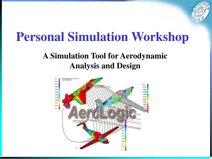
Personal Simulation Workshop A Simulation Tool for Aerodynamic Analysis and Design
Personal Simulation Workshop (PSW):Digital Wing Tunnel (DWT) • PSW is a streamline-body design and analysis package for the PC, comprising programs for surface definition, flow analysis, and data visualization. • Its three principal elements : • Loftsman • geometric layout of external lines • Cmarc • flow analysis • Postmarc • interpretation of results
Introduction to Cmarc • An inviscid fluid flow analysis code of the type known as a low-order panel method. • It is an enhanced version of NASA's Pmarc-12 • With modern desktop computers, dense meshes of 5,000 or more panels for a half-model can be analyzed in minutes. • Although the basic analysis is inviscid, a subsequent boundary-layer analysis may be performed along individual streamlines or over the entire surface. • Provided that flow is attached and that large areas of crossflow do not appear, the boundary layer analysis is quite accurate. • Only the frictional and lift-induced components of drag can be computed, however; an inviscid analysis is inherently unable to calculate pressure or "form" drag. • Written in ANSI C
The CMARC input fileGeneral format • The file uses a Fortran NAMELIST format in which variable names are joined to values by equals signs. • Each line begins with an ampersand (&) in the second column and ends with &END. • The first column is empty. • Line feeds are ignored, and an input line may extend over several physical lines. • A generic line might look like this: &DATA VAR1=2, VAR2=0, VAR3=0, &END • The commas may be omitted.
The CMARC input fileUnits • Any units of measure may be used, but they must be consistent throughout. • For example, if the body geometry is defined in inches, all speeds should be in inches per second rather than feet per second or miles per hour.
The CMARC input fileAxes and rotations • A conventional coordinate system is used • X representing the longitudinal axis and increasing aft • Y the spanwise axis increasing to the starboard • Z the vertical axis increasing upward. • All rotations are performed in accordance with the right hand rule.
The CMARC input file • Theinput file consists of three major sections • general run control information • body and wake geometry • parameters for special services • velocity scans, streamlines, etc.
General run control information • Name and output instructions: &BINP2 and &BINP3 • Solver parameters: &BINP4 • Time-step parameters -- &BINP5 • Symmetry and computation parameters -- &BINP6 • Free stream conditions -- &BINP7 • Angular position and rotation rates -- &BINP8 • Rotational oscillatory motion -- &BINP8A • Translational oscillatory motion -- &BINP8B • Reference dimensions -- &BINP9 • Special options -- &BINP10 • Normal velocity specification -- &BINP11 • Panel tilt -- &BINP11A • Panel neighbor information change -- &BINP12 • Boundary layer calculation control -- &BINP13
General Run Control Information The format is: WING BODY COMBINATION TEST CASE &BINP2 LSTINP=2, LSTOUT=0, LSTFRQ=0, LENRUN=0, LPLTYP=0, &END &BINP3 LSTGEO=0, LSTNAB=0, LSTWAK=0, LSTCPV=0, &END &BINP4 MAXIT=200, SOLRES=0.0005, &END &BINP5 NTSTPS=3, DTSTEP=30.0, &END &BINP6 RSYM=0.0, RGPR=0.0, RFF=5.0, RCORES=0.050, RCOREW=0.050, &END &BINP7 VINF=1.0, VSOUND=13392.0, &END &BINP8 ALDEG=4.0, YAWDEG=0.0, PHIDOT=0.0, THEDOT=0.0, PSIDOT=0.0, &END &BINP8A PHIMAX=0.0, THEMAX=0.0, PSIMAX=0.0, WRX=0.0, WRY=0.0, WRZ=0.0, &END
&BINP8B DXMAX=0.0, DYMAX=0.0, DZMAX=0.0, WTX=0.0, WTY=0.0, WTZ=0.000, &END &BINP9 CBAR=61.25, SREF=14400.0, SSPAN=120.0, RMPX=200.00, RMPY=0.00, RMPZ=0.00, &END &BINP10 NORSET=0, NBCHGE=0, NCZONE=0, NCZPCH=0, CZDUB=0.0, VREF=0.0, &END &BINP11 NORPCH=0, NORF=0, NORL=0, NOCF=0, NOCL=0, VNORM=0.0, &END &BINP12 KPAN=0, KSIDE=0, NEWNAB=0, NEWSID=0, &END &BINP13 NBLIT = 1, &END
Body Geometry • The hierarchy of geometrical entities • Point > Section > Patch > Component > Assembly. • Each component or assembly is represented by a mesh of rectangular and, occasionally, triangular panels. • Panels are grouped in patches, which are rectangular arrays of panels. • The surface of a model is composed of one or more patches. • A patch may consist of a single panel.
Body Geometry • Coordinate systems • The first entries in the geometry section define the coordinate systems for each of the components and assemblies in the model. • Each component or assembly has an &ASEM1 or &COMP1 line defining the origin of its local coordinate system. • If the coordinate system of the item is to be rotated about an axis other than the Y axis of the assembly coordinate system, an &ASEM2 or &COMP2 line is required as well.
&ASEM1 ASEMX=143.0000, ASEMY=25.0000, ASEMZ=-11.0000, ASCAL=-1.0000, ATHET=35.0, NODEA=0, &END &ASEM2 APXX=145.25, APYY=25.0000, APZZ=-10.1300, AHXX=137.7700, AHYY=140.0, AHZZ=-8.563, &END &ASEM1 ASEMX=135.0000, ASEMY=140.0000, ASEMZ=-8.0000, ASCAL=1.0000, ATHET=0.0, NODEA=5 &END &COMP1 COMPX=0.0000, COMPY=0.0000, COMPZ=0.0000, CSCAL=1.0000, CTHET=0.0, NODEC=5, &END • The meanings of the variables are as follows: ASEMX, ASEMY, ASEMZ Origin of the assembly coordinate system in global coordinates. (R) ASCAL Scale. If ASCAL is negative, a rotation axis other than the Y axis must be defined in ASEM2. (R) ATHET Rotation angle of the assembly in degrees, using the right hand rule, eg downward deflection of a flap on a right wing is positive. The rotation axis is the assembly Y axis unless ASCAL is negative. (R) NODEA If NODEA is 0, another assembly is defined after this one. If NODEA is 5, this is the last assembly to be defined. (I) APXX, APYY, APZZ Starting point of the rotation axis in unscaled assembly coordinates. (R) AHXX, AHYY, AHZZ Ending point of the rotation axis. (R) Corresponding variables in a component block begin with C or COMP rather than A or ASEM, but have the same meanings.
Body Geometry • Panels • The basic surface element is called a panel. • Panels are defined as rectangles. • A panel that is triangular in shape is actually a rectangle with two corners that coincide. • Panels may not have zero area. • No gaps between panel • Small in areas of small curvature • Larger in flatter aeras • 1000 panels for wing • 1,500-5000 panels per side for full models
Body Geometry • Patch definition • The numbers of panels in the rows and columns of the rectangular array forming a patch is constant across the width and height of the patch. • While patches are considered for convenience to be rectangular in shape, they can be distorted in various ways. • The row and column counts would be constant throughout the patch. • Columns of panels in a patch are defined by "sections."
Body Geometry • Patch orientation and point, section and panel numbering • Patches have two surfaces, an outside and an inside. They are distinguished by the order in which section and basic point data are entered. • right hand method • patches are generally arranged from nose to tail, and, from bottom to top. • Panel numbering • lower right corner panel of a patch is number 1; number 2 is above it; and so on to the to edge of the patch. • Numbering then returns to the bottom of the second column and continues.
Body Geometry • Folded patches • Patches may be folded over so that their opposite edges coincide. • Wing surfaces are typically defined in this way • The trailing edge thickness must be zero and the spanwise positions of basic points along the coincident edges must also coincide.
Body Geometry • Patch description • Each patch description begins with an &PATCH1 line followed by a line containing the patch name. &PATCH1 IREV=0, IDPAT=1, MAKE=0, KCOMP=1, KASS=1, IPATSYM=0, IPATCOP=0, &END The meanings of variables are as follows: IREVPatch reversal flag. If IREV is 0, the patch is not reversed; that is, the given point order is used. If IREV is -1, the inside/outside orientation implied by the order of point and section entry is reversed. See the discussion of duct flow below for some practical instances of patch reversal. (I) DPAT Patch type. Three values are possible. 1 indicates a wing; section force and moment data are generated. 2 indicates a body; no section data are generated. 3 indicates a Neumann patch or vortex lattice sheet. (I)
MAKE If MAKE is a positive integer n, CMARC automatically generates a wingtip on side 3 of patch n. This is the normal arrangement with a starboard wing. If MAKE is negative, the wingtip patch is generated on side 1 of the patch (left wing). For all patches other than automatically generated tip patches, MAKE should be 0. If MAKE is non-zero, a &PATCH2 line must follow this line. [I] KCOMP The number of the component to which the patch belongs. Zero defaults to 1. [I] KASS The number of the assembly to which the patch belongs. Zero defaults to 1. [I] IPATSYMIf IPATSYM is 1, another patch is generated, mirroring this one about the XZ plane of symmetry. The mirror patch is numbered immediately following this one. If no symmetrical copy is to be generated, IPATSYM is zero. The section order of mirrored patches is the same as that of their prototypes, but the point order within sections is reversed. (I) IPATCOPIf IPATCOP is a positive integer n, then this patch is an optionally translated, scaled and/or rotated copy of a previously defined patch whose sequential number is n. A &PATCH3 line, defining the rotations for the copied patch, must follow the patch name line whenever the value of IPATCOP is non-zero.
Body Geometry • Section format • Each section in a patch may take one of three forms: • a list of basic points • a NACA 4-digit airfoil • a line of revolution. • Each section may be defined in terms of • the global coordinate system • its own local coordinate system.
Body Geometry • Section format • Each section begins with an &SECT1 line in the following format: &SECT1 STX=0.0, STY=0.0, STZ=0.0, SCALE=1.0, ALF=0.0, THETA=0.0, INMODE=4, TNODS=0, TNPS=0, TINTS=0, &END here is one point to a line, defined by three coordinates without delimiters other than one or more spaces: 142.8305 0.0000 -15.6029 142.8305 4.9666 -14.7913 142.8305 9.2749 -12.5468 142.8305 12.5615 -9.2550 142.8305 14.7977 -4.9475 142.8305 15.6029 0.0000 • Each basic points list ends with a &BPNODE line, which identifies a break point. &BPNODE TNODE=3, TNPC=0, TINTC=0, &END
STX, STY, STZOrigin of the section coordinate system in component coordinates. (R) SCALESection scale. If SCALE is 0.0, the section becomes a single point at the origin of the coordinate system. (R) ALF Rotation in degrees of the section coordinate system about its Y axis. (R) THETA Rotation angle of the section coordinate system about its Z axis. (R) INMODEMay have the following values (I): 0. Copies the definition of the previous section. 1. The section is defined by Y, Z, dX coordinates. The X coordinate defaults to 0.0 in the local coordinate system, but deviations can be entered in dX. 2. The section is defined by X, Z, dY coordinates. The Y coordinate defaults to 0.0 in the local coordinate system, but deviations can be entered in dY. 3. The section is defined by X, Y, dZ coordinates. The Z coordinate defaults to 0.0 in the local coordinate system, but deviations can be entered in dZ. 4. The section is defined by X, Y, and Z coordinates. (This is the most commonly used option.) 5. A NACA 4-digit airfoil section is automatically generated. A &SECT2 line must follow this one
TNODS Defines section type. TNODS may have the following values (I): 0. This is the first section or an intermediate section in the patch. 1. This is a break point on a patch. The slope is continuous into the next portion of the patch. 2. This is a break point on a patch. The slope is discontinuous into the next portion of the patch. 3. This is the last section in this patch. 5. This is the last section in the last patch in the geometry definition. Any subsequent sections are ignored. TNPS If TNPS is zero, panel corners are defined by the basic points lists given. If TNODS is 1 or 2 and TNPS is a positive integer, TNPS is the number of panels that will be automatically inserted between this break point and the previous break point, using curvilinear interpolation based on the points you have supplied. TINTS As in the &PATCH2 line, TINTS controls the type of spacing for automatically inserted panels. The possible values are 0 for full cosine spacing, 1 for half cosine with smaller panels near the previous break, 2 for half cosine with smaller panels near this break, and 3 for equal spacing. If INMODE is 4, this is ignored. Often INMODE is 4 and TNPS is zero, and the &SECT1 line is followed by a list of basic points.
TNODE If TNODE is zero, the preceding point is a first or intermediate point. The rest of the &BPNODE line is ignored. If TNODE is 1, the preceding point is a break point with a continuous slope into the next region of the section. If TNODE is 2, the slope is discontinuous. A value of 3, which is the most commonly seen, indicates that the preceding point is the last one in this section. TNPC Indicates the number of points to be automatically generated between this break point and the preceding one. Zero indicates that no point generation will take place, and instead the given basic points will be used as panel corners. [I] TINTC Spacing of automatically generated points. The possible values are 0 for full cosine spacing, 1 for half cosine with smaller panels near the previous break, 2 for half cosine with smaller panels near this break, and 3 for equal spacing. [I]
Body Geometry • Automatic wingtip patch generation • If MAKE in the &PATCH1 line has a non-zero value, a &PATCH2 line follows the &PATCH1 line. • 2 in &PATCH2 refers to a type of patch definition, namely a wingtip patch, not to the sequential order of patches. • The &PATCH2 line has the following appearance: &PATCH2 ITYP=1, TNODS=3, TNPS=3, TINTS=3, &END
ITYP Type of tip patch. 1 indicates a flat tip. 2 indicates a circular arc cross-section in the YZ plane. (I) TNODS If TNODS is 3, more patches follow this one. If TNODS is 5, this is the last patch to be read in the geometry input. If others follow, they are ignored. Misbehaving input files can be tested by repeatedly running them through CMARC, moving TNODS=5 down through the file patch by patch until encountering the cause of the difficulty. (I) TNPS The number of panels across the tip. (I) TINTS TINTS determines the method of spacing panels across the tip. There are four options: [I] 0. Full cosine spacing, ie panels narrow at the edges of the patch and wide at the middle. 1. Half cosine spacing with narrow panels near the beginning of the tip patch. For a starboard wing, this would be the lower edge. 2. Half cosine spacing with narrow panels near the end of the patch, ie the upper edge on a starboard wing tip. 3. Equal spacing. This is usually the logical choice.
The Format of Body Geometry:wing-body example &ASEM1 ASEMX= 0.0000, ASEMY= 0.0000, ASEMZ= 0.0000, ASCAL= 1.0000, ATHET= 0.0, NODEA= 5, &END &COMP1 COMPX= 0.0000, COMPY= 0.0000, COMPZ= 0.0000, CSCAL= 1.0000, CTHET= 0.0, NODEC= 5, &END &PATCH1 IREV=0, IDPAT=1, MAKE=0, KCOMP=1, KASS=1, IPATSYM=0, IPATCOP=0, &END WING (Patch 1, 10x218) &SECT1 STX=0.0, STY=0.0, STZ=0.0, SCALE=1.0, ALF=0.0, THETA=0.0, INMODE=4, TNODS=0, TNPS=0, TINTS=0, &END 214.7273 16.5846 0.0000 213.8503 16.5982 -0.0393 211.2598 16.6341 -0.1770 207.0737 16.6744 -0.5111 ……….. ……… ………
………. ……… ……… 163.5382 16.1903 1.9466 171.1906 16.3499 2.1004 179.2087 16.4867 2.1022 187.1898 16.5913 1.9359 194.7429 16.6653 1.5224 201.4814 16.6924 0.9932 207.0737 16.6744 0.5111 211.2598 16.6341 0.1770 213.8503 16.5982 0.0393 214.7273 16.5846 0.0000 &BPNODE TNODE=3, TNPC=0, TINTC=0, &END &SECT1 STX=0.0, STY=0.0, STZ=0.0, SCALE=1.0, ALF=0.0, THETA=0.0, INMODE=4, TNODS=3, TNPS=10, TINTS=0, &END 298.7515 120.0000 0.0000 298.1874 120.0000 -0.0150 ………. ……… ……… &BPNODE TNODE=3, TNPC=0, TINTC=0, &END
WING_TIP (Patch 2, 56,336) &PATCH2 ITYP= 2, TNODS= 3, TNPS= 4, TINTS= 3, &END &PATCH1 IREV=0, IDPAT=2, MAKE=0, KCOMP=1, KASS=1, IPATSYM=0, IPATCOP=0, &END ROOT TRANSITION FORE STARBOARD (Patch 3, 336,120) &SECT1 STX=0.0, STY=0.0, STZ=0.0, SCALE=1.0, ALF=0.0, THETA=0.0, INMODE=4, TNODS=0, TNPS=0, TINTS=0, &END 0.0000 0.0000 0.0000 0.0000 0.0000 0.0000 ……… ……… ……… 0.0000 0.0000 0.0000 &BPNODE TNODE=3, TNPC=0, TINTC=0, &END &SECT1 STX=0.0, STY=0.0, STZ=0.0, SCALE=1.0, ALF=0.0, THETA=0.0, INMODE=4, TNODS=0, TNPS=0, TINTS=0, &END 2.4334 0.0000 -1.8955 2.4334 0.6149 -1.7929 ……… ……… ……… 2.4334 0.0000 1.8955 &BPNODE TNODE=3, TNPC=0, TINTC=0, &END
Wake Geometry Section • Function of wakes • In order for a surface to produce lift, flow must be prevented from circulating around the trailing edge. • CMARC uses an imaginary membrane called a "wake" to separate upper-surface from lower-surface flow. • The wake may be thought of as the “downwash sheet”. • If no wake is provided for a lifting surface, the pressure distributions on it and on the rest of the model will be incorrect.
Wake Geometry Section • Several options for dealing with the wake. • fully pre-defined • generated by CMARC from a separation line specified by the user. • rigid or flexible. • The number of time steps in wake development, and their duration, may be defined. • When VINF is 1.0, it is convenient to set the time step roughly equal to the wing chord measured in the default unit
Wake Geometry Section • Wake geometry definition • Wake name • Wake separation line • Wakes with specified initial geometry
Wake geometry definition • Wake geometry begins with a &WAKE1 line, followed by a wake name (analogous to the body name) and a &WAKE2 line defining the geometry of the wake-body attachment. The format is as follows: &WAKE1 IDWAK=1, IFLXW=0, ITRFTZ=1, INTRW=1, &END WING/BODY WAKE &WAKE2 KWPACH=7, KWSIDE=4, KWLINE=6, KWPAN1=0, KWPAN2=0, NODEW=0, INITIAL=1, &END &WAKE2 KWPACH=1, KWSIDE=2, KWLINE=0, KWPAN1=0, KWPAN2=0, NODEW=5, INITIAL=1, &END
IDWAKIf IDWAK is zero, no wake is defined. If a wake is defined, IDWAK must be 1. [I] IFLXWZero indicates a flexible wake that will be time-stepped with the local velocity. 1 indicates a rigid wake that will be time-stepped with the freestream velocity only. [I] ITRFTZA value of zero or 1 indicates that the wake separation line will be used for the Trefftz plane computation of induced drag for this wake. A higher value specifies the row of wake panels that will be used for induced drag computation. If ITRFTZ exceeds the number of rows of panels in the wake, its value defaults back to 1. Normally, ITRFTZ should be set to a position one or two panels ahead of the end of the wake. [I] INTRWZero indicates that wake panels will not be checked for penetration of a surface before velocity calculations are made for flexible wakes. 1 indicates that the intersection checking routine is turned on. [I]
Wake separation line/&WAKE2 • The line (“WSL”) along which the wake separates from the body is defined by one or more &WAKE2 lines. • The line may begin at the plane of symmetry or at a wingtip, but it must progress continuously in the same direction throughout its definition. • The wake should extend all the way to the plane of symmetry; otherwise a second set of tip vortices will form on the inboard edges of the wake. • Each &WAKE2 line defines a portion of the WSL within a single patch. There must be as many &WAKE2 lines as there are patches through which the WSL separation line passes.
KWPACH The sequential number of the patch from which this portion of the wake separates. (I) KWSIDE The side of the patch that is parallel to and progressing in the same direction as the WSL. KWSIDE must have a value of 1, 2, 3, or 4. The "direction" of the sides refers to the counterclockwise progress of edge numbers around the patch. Thus, the direction of the upper-surface trailing edge of a starboard wing (patch edge 2) is outboard. (I) KWLINEThe number of the row or column within the patch from which the wake separates. Most panel edges are shared by two panels; the panel that "owns" the separation line is the one on which the edge corresponding to the WSL has the same direction as the WSL itself. Another way to put it is to imagine a bug walking along the WSL in the direction of its propagation. The panel that owns the WSL lies to the bug’s left. A value of zero indicates the panel edge opposite to the one having the appropriate direction. (I) KWPAN1The number of the column or row beside which this segment of the wake separation line begins. Panels are counted in the direction of progression of the wake separation line. A value of zero defaults to the first column or row. [I]
KWPAN2 The number of the column or row beside which this segment of the separation line ends. Panels are counted in the direction of progression of the wake separation line. A value of zero indicates the last column or row in the patch. (I) NODEW Zero indicates that another &WAKE2 line follows to further define the separation line. 3 indicates that this wake separation line is now complete but there are more wakes to be defined. 5 indicates that this is the last wake and its separation line has now been completely defined. INITIAL If INITIAL is zero, no initial wake geometry is specified. A value of 1 indicates that an initial geometry will be specified, and must be followed immediately by an &SECT1 line.
Wakes with specified initial geometry A wake whose initial geometry is specified is defined by a series of transverse cross-sections. An &SECT1 line for a wake is almost identical to one for a body surface patch. The format is as follows: &SECT1 STX=0.0, STY=0.0, STZ=0.0, SCALE=1.0, ALF=0.0, THETA=0.0, INMODE=4, TNODS=0, TNPS=0, TINTS=0, &END
Example: Wing-Body &WAKE1 IDWAK=1, IFLXW=0, ITRFTZ=1, INTRW=1, &END WING/BODY_WAKE &WAKE2 KWPACH=6, KWSIDE=4, KWLINE=6, KWPAN1=0, KWPAN2=0, NODEW=0, INITIAL=1, &END &WAKE2 KWPACH=1, KWSIDE=2, KWLINE=0, KWPAN1=0, KWPAN2=0, NODEW=5, INITIAL=1, &END &SECT1 STX= 1225.0000, STY= 0.0000, STZ= 0.0000, SCALE= 1.0000, ALF= 0.0, THETA= 0.0, INMODE=-1, TNODS= 3, TNPS= 20, TINTS= 3, &END
Execution options • Streamlines: don’t bother • On-body streamlines • Boundary layer parameters • Off-body velocity scans • Rectangular scan volumes • Cylindrical scan volumes • Off-body streamlines
On-body streamlines • The wake definition portion of the input file is followed by the on-body streamlines definition. • The definition consists of a single line which must be present even if no on-body streamlines are to be calculated. • The format of the line is as follows: &ONSTRM NONSL= 5, KPSL= 323,325,327,329,331, &END NONSL The number of on-body streamlines to be defined. This may be zero. (I) KPSL A list of the numbers of the panels from whose centers the streamlines originate. Panel numbers may be obtained most conveniently from a geometry display in POSTMARC. (I)
Boundary layer parameters • If NBLIT=1 in the &BINP13 line in the basic input page, a line of the following format must follow the on-body streamline specification. &BLPARAM RN=1640000, VISC=0.02304, NSLBL=1,2,3,4,5, &END RN Reynolds number. This must be based on the reference chord (CBAR) and the freestream velocity (VINF) given on the basic input page, and on VISC. VISCDimensional kinematic viscosity in the same units as the global geometry, eg 0.00016 for feet, 0.02304 for inches, etc. NSLBL The sequential numbers of the streamlines on which boundary layer calculations are to be performed. Streamlines are numbered from 1 to NONSL (in the &ONSTRM line above).
Off-body streamlines • Off-body streamlines may be traced by specifying a point along the streamline and the distances upstream and downstream that the streamline is to be traced. • The entry format is the following: &SLIN1 NSTLIN=2, &END &SLIN2 SX0=20.0000, SY0=50.0000, SZ0=-5.000, SU=0.0000, SD=150.0000, DS=1.0000, INTSL=1, &END &SLIN2 SX0=20.000, SY0=50.000, SZ0=-3.0000, SU=0.000, SD=180.0000, DS=1.0000, INTSL=1, &END • The &SLIN1 line tells the number of streamlines that will be defined. It must be followed by as many &SLIN2 lines as there are streamlines
NSTLNNumber of streamlines to be defined. (I) SX0, SY0, SZ0 Coordinates of a point on this streamline. (R) SU Distance to trace the streamline in the upstream direction. SD Distance to trace the streamline in the downstream direction. DS Step size. INTSL If zero, no checking is performed to see whether streamline points have penetrated a surface. If 1, each point is checked before velocity calculations are performed.