Download
1 / 42
430 likes | 575 Views
Lecture 6 Central Processing Unit. Lecture 5: Central Processing Unit. In this lecture, we will study Functional Components of CPU Flags Registers Design Issues Types of Registers Data Registers AC Machine GPR Machine Stack Machine Address Registers(Next lecture)

E N D
Lecture 6Central Processing Unit Central Processing Unit
Lecture 5:Central Processing Unit In this lecture, we will study • Functional Components of CPU • Flags • Registers • Design Issues • Types of Registers • Data Registers • AC Machine • GPR Machine • Stack Machine • Address Registers(Next lecture) • Control and Status Registers(Next lecture) Central Processing Unit
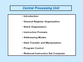
CPU In this lecture, we will study(Continue) • Storage • Data register • Address Register • Index Register • Base Address Register • Page/Segment Address Register • Stack Pointer • Control and Status Register • Program Status Word • ALU • Adder, Logic Unit, Shifter • Bus(Internal Bus) • ALU Input Bus and Output Bus Central Processing Unit
Input Bus 1 Input Bus 2 Control Unit Flags Registers ALU Output Bus CPU Functional Components of CPU 4 kinds of resources in CPU • Storage Function • Registers, Flags(for storage of status and conditions), (Stack if any) • Processing Function • (ALU)Arithmetic Logic Unit(Adder + Shifter + Boolean) • Transfer Function • Internal Bus(ALU Input Bus, ALU Output Bus) • Control Function • Hardwired or Microprogrammed control unit Central Processing Unit
Registers and Flags Characteristics • Faster than memory or cache • On the same chip as the CPU(same circuit) • Access(Read from or Store into register) in a gate delay • Register file is physically small • Modern computers have a lot of registers • 32, 64, 128, …growing • But still not enough to store the information that CPU needs immediately • Shorter address than main memory • Number of registers is not large • Decoding delay of address is short Central Processing Unit
CPU Flags • 1_bit flags to represent the status of the results of the latest arithmetic instruction executed • Result Overflow - O flag • Sign of the result - S flag • Result is zero - Z flag • Carry from MSB - C flag • etc • 1_bit flags representing the status of CPU • Interrupt enable/disable - IE • Interrupt requested – IRQ • Running Supervisor/User Mode program - S/U • Modern computers includes Program Status Word(s) to include these flags • PSW Central Processing Unit
Registers Fastest Storage in the computer system • Expensive Storage • Cannot have as much as you like • Register address is shorter than memory address, thus results in a shorter instructions • In a CPU • Access in a gate delay • Temporary storage • Avoids memory accesses for intermediate operands and temporary results • Different procedures use the same registers • Registers need to be save in the memory and restored from the memory when execution switches from one procedure to another • Needs for a Context Switch • Context switch time depends on the size of the context, i.e., the number of registers and flags Central Processing Unit
Procedure A RETURNto A CALL B Running Procedure Procedure B Procedure A Register File Store Context A Store Context B Load Context A Load Context B Memory Context A Context B Context Switch Central Processing Unit
Context Switch Assume that the context consists of n registers Saving context ST R0, X ST R1, X+1 ST R2, X+2 … ST Rn-1, X+(n-1) Restoring context LD R0, Y LD R1, Y+1 LD R2, Y+2 … LD Rn-1, Y+(n-1) With this type of instructions, context switch consumes a lot of Memory Bandwidth - Need for an instruction set that supports faster context switch - Multiple register LD and ST LD R0, Rn-1, Y ST R0, Rn-1, X Central Processing Unit
Registers vs Memory • Memory - Stores Program and Data to be runRegisters - Stores Operands used by the instruction being executed - Stores the Results of executed instructions • To save the stored information; Memory - In the Secondary storage Registers - In the Main memory, (then Secondary storage) • To access; Memory - Address, usually represented by a large number of bits Registers - Register Number, much shorter than memory addresses • Speed; Memory - Access Time Registers - Gate delay in CPU Central Processing Unit
E.g. 32 registers 5-bit address If dedicate half to Data and another half to Address 4-bit addresses Dedicate 1 register to BAR, IX No need to specify address Design Issues on Registers • Specialization(Dedication) vs Generalization • Specialization allows implicit specification of the address(less bits for instruction) • If registers are dedicated, usually dedicated to Data Registers and Address Registers • e.g. BAR, IX, …, to store address only • Limits programming flexibility • Number of Registers • Somewhere between 8~32 appears optimum • Fewer - more memory accesses • More - do not noticeably reduce memory accesses • Register Length • Address Register: Largest address • Data Register: Most data types Central Processing Unit
Types of Registers • Application • General Purpose Register • Dedicated Application Registers • Data register • Address register • Control register • Visibility • User-visible registers • Enables programmer to minimize main memory references by an optimal use of registers • User-invisible registers • User cannot access(use) directly in the program Central Processing Unit
Types of Registers • General Purpose Registers(GPR) • Registers are not dedicated to a particular application • Can be assigned to a variety of functions by programmers • Data Registers • May only be used to hold data • Address Registers • Somewhat general purpose, or may be devoted to a particular address mode • Segment pointer, Page address • Index Register(IX), Stack Pointer, Base Address Register(BAR) • Control and Status Registers • PSW • Zero, Sign, Overflow, Carry, ... Central Processing Unit
Data Registers • Accumulator(AC) • Single Data Register • AC Machine • Multiple data registers • General Purpose Register • Multiple dedicated data registers • GPR Machine • Stack • Associated with a Calculation Stack • Stack Machine Central Processing Unit
Time Out • 교수 회의에서 나온 말 • “어침 8시 강의를 맡은 우리는 두 가지 어려운 점이 있습니다. 하나는 출석률이 낮은 것이고, 또 하나는 창 밖에서 잔디 깎는 소리 때문에 강의를 제대로 들을 수 없다는 것입니다.” • 한 교수가 웃으면서 대안을 제시했다. • “잔디를 7시에 기숙사 밖부터 깎게 하면 어떨까요?” Central Processing Unit
Other non-data Registers AC ALU AC Classification of CPU by Data Registers:AC Machine • There is only one data register called AC • AC is considered as a part of ALU • Remember that ALU is a combinational logic circuit, thus do not have memory to hold any operand • One of the two operands is always in AC • The result of the operation is always stored in AC, but it can also be stored in a temporary register(T) • The operand address AC can be implied(omitted) in the instruction • Instruction length becomes short • Frequent memory access using Load(LDA) and Store(STA) instructions Central Processing Unit
General Purpose Registers General Purpose Registers ALU Classification of CPU by Data Registers:GPR Machine • Any number of registers in GPR can be used as data registers • ALU does not have memory to store any operand, thus GPR provides them • Frequency of using Load/Store instructions can be low - LD and ST • Operands are from GPR, and the result goes to a GPR • The operand(GPR) addresses are shorter than memory address • Instruction length becomes short • Memory access frequency may be low but data must be loaded to registers before using them Central Processing Unit
From Memory General Purpose Registers ALU Stack Stack To Memory Classification of CPU by Data Registers:Stack Machine • Only registers in the stack are used as data registers • Load(PUSH)/Store(POP) instructions to load into the stack or store from the stack are needed • Operands are available from stack, and the result of operation is stored into the stack • The operand addresses can be omitted • Instruction length becomes short • Memory access frequency may be low but data must be loaded to stack before using them Central Processing Unit
Shift Right (ALU) ADD (ALU) SP SP Stack Operations- Arithmetic Operations - Unary Operation • e.g. Shift Right 1 bit Binary Operation - e.g. ADD Central Processing Unit
PUSH X (SP SP+1, S[SP] M[X]) POP X (M[X] S[SP], SP SP-1) Stack Operations- Load and Store Operations - Load Operation Using Push Store Operation Using POP Central Processing Unit
Address Registers • General Purpose Register • Dedicated Address Registers Somewhat general, but some are dedicated to a particular addressing modes • Program Address Counter(PC) • Index Register(IX) • Base Address Register(BAR) • Stack Pointer(SP) • Page Address Register(P) • Segment Address Register(S) Central Processing Unit
149 A = S Ai using ADD X , which does AC AC + M[X] i=0 100 101 102 103 104 . . . 148 149 A0 A1 A2 A3 A4 A148 A149 AC 0 X 100 LOOP ADD X if X GE 149, then end LDA LOOP INC STA LOOP JMP LOOP AC 0 LOOP ADD 100(IX) if IX GE 49, then end (INC IX) JMP LOOP When get out of the loop Index Register ADD 100instruction does not change. But the value in IX changes. Further reduction by auto index register ADD Xinstruction changes to ADD (X+149). Unreliable program Central Processing Unit
BAR BAR 500 [BAR] 100 101 102 103 104 … 100+X . 148 149 A0 A1 A2 A3 A4 AX A148 A149 A0 A1 A2 A3 A4 AX A148 A149 500 501 502 503 504 … 500+X . 548 549 X + Relocation Base Address Register 100 ADD X(BAR) Central Processing Unit
Page/Segment Address Register • Page • A fixed number of contiguous words in memory • A physical division of memory space • Segment • A variable number of contiguous words in memory • A logical division of program Page/Segment addressing is basically a relative addressing method. Similar to Base Address + Displacement with BAR replaced by P/S. Page Address Register + Displacement within a page Segment Address Register + Displacement within a segment Central Processing Unit
PC Sign Zero Carry Overflow Interrupt Enable Interrupt Request User/Supervisor PC IR MAR MBR PSW: Program Status Word Used to move information between CPU and Memory Control and Status Registers • Registers to control the operation of CPU - Control Unit • Registers to control the execution of programs - Privileged OS PSW may also includes; Pointer to PCB(Process Control Block) in MM for additional status information Interrupt Vector Registers System Stack Pointer Page table Pointer Central Processing Unit
PSW: Program Status Word State of a sequential logic circuit => States of F/Fs(Reg) in the circuit When an instruction is being executed, some of the registers and flags change the information stored in them => Change the state of CPU Program Status Word(PSW) PSW represents the state of the running program collectively • PC: Represents how far program progressed • Registers: All the information stored in the registers by the running program • Condition Code: Result of arithmetic calculation • O, C, Z, S, etc • Other information needed to control the execution of program Central Processing Unit
Time Out • 화장실 문 안쪽에 쓰여 있는 글 • “당신이 지금 사색(思索)을 즐기고 있는 동안 밖에 있는 사람은 사색(死色)이 되어가고 있습니다. Central Processing Unit
A General Purpose Register Structure: Z8000 Register Structure • 16-bit general purpose register machine • R0 ~ R15 • Used for data, address, and indexing • R14(system mode) and R15(normal mode) - SP • Registers can be used for 8-bit ~32-bit operations • Segmented Address Space • 7-bit segment address and 16-bit offset - 2 registers for an address • Program Status Registers • PC segment and PC offset • Program Status Area(PSA-memory) segment and PSA offset • Flag Control Word - Status and Control bits Central Processing Unit
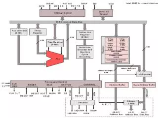
} } Offset Address Registers } Segment Base A Dedicated Register Structure: Intel 8086 Register Structure • 4 x 16-bit Data Registers • Addressable on a byte or on a 16-bit word • Somewhat general purpose uses • In some instructions, the use is dedicated so that it can be implied • AX(AC), BX(Base Address), CX(counter), DX(Data) • 4 x 16-bit Pointers and Index • SP: Stack Pointer • BP: Base Pointer • SI: Source Index • DI: Destination Index • 4 x 16-bit Segment Registers • CS: Code • DS Data • SS: Stack • ES: Extra • 16-bit Instruction Pointer and 16-bit Flags(set of 1-bit flags) Central Processing Unit
Dedicated and General Purpose Registers:MC68000 Register Structure • Data Registers • 8 registers • D0 ~ D7 • Address Registers • 9 registers • A0 ~ A7, A7’ • A7: User stack pointer • A7’: Supervisory stack pointer • Program Status • Program Counter (32-bit) • 16-bit Status Register Internal and External Buses and ALU are 16-bit, Registers are 32-bit(concatenation of 2 16-bit) It is a GPR machine; Division of Data and Address Registers is for saving 1 bit on each register address specification. Central Processing Unit
R1 ... R1’s life R3 f(R1, …) … R1 is not used here R1 [ ] Issues on the Number of Registers Needs to evaluate following in terms of Time Used or Time Saved by having or not having enough registers • How many registers are used simultaneously? • How many would be sufficient most or all of the time? • What would be overhead if the number of registers were reduced? • In what purpose the registers were used during their lives? Register Life All activities associated with a given register during a period of time, starting with a load and terminating with the last use before the next load. - A register is dormant when it is live but not used - A register is dead when it had been dormant for k or more instructions Central Processing Unit
Study with DEC 10 ISP 16 GPR 41 Programs with different languages • Most lives are 2 ~ 7 instructions long(only 4% are 32 instructions long) • Average life length is 11.9 • Average references to a live registers is 4.2(3 ~ 7) • Average number of simultaneous live registers is 2 ~ 6 • Average 39%(18 ~ 68%) of the lives are used for indexing • No program uses more than 15 registers simultaneously • 17 out of 41 programs would get by with less than 10 registers(10 registers would suffice 90% of time) • If registers were to be dedicated • 2 Floating point accumulators • 2 Fixed point accumulators • 10 index registers Central Processing Unit
Save(Store) in the memory, but may not need to restore(Load) Reduction of Number of Registers • M: Number of registers in the computer • N: Number of registers required simultaneously • M < N Need to store and restore registers • Results in increase in execution time • Upper Bound on Increase in Execution Time • Interleaving • N-M least usefullives to be stored in memory • Each reference to these registers cost at the most 2 LD/ST pairs Currently R1 stores A We need to use R1 to store B Now: Save A in R1 for later use - 1 ST Retrieve B to store in R1 - 1 LD Later: Retrieve A to store in Ri - 1 LD Save the value in Ri - 1 ST • Criteria for least usefulness - lives with low overhead can be selected • Number of references to the life was high(use of this register may be over) • Density of references to the life was high( “ “ “ ) • The life was long(Remaining life may be short) • The life was short(Remaining life could be long) • Bedding • Based on the local properties of lives, save registers in memory when they have long dormant period(time k), at the cost of 1 pair of ST/LD(Low cost) - save in memory butmay not need to restore Central Processing Unit
Cc Cr X7 Y7 X6 Y6 X5 Y5 X4 Y4 X3 Y3 X2 Y2 X1 Y1 X0 Y0 C C S7 S6 S5 S4 S3 S2 S1 S0 FA FA FA FA FA FA FA FA Cm DI C0 A Arithmetic and Logic Unit:Adder Central Processing Unit
A Cm C0 DI Cc Cr Control of Adder Add 1 0 0 1 0 0 2’s Compl Add 1 1 1 1 0 0 1’s Compl Add 1 1 0 1 0 0 Increment AC 1 0 1 0 0 0 Compl AC 1 1 0 0 0 0 Clear Carry 0 d d d 0 1 Compl Carry 0 d d d 1 0 Central Processing Unit
Ri S7 S6 S5 S4 S3 S2 S1 S0 Ro Z7 Z6 Z5 Z4 Z3 Z2 Z1 Z0 Lo Li NS LS RS SE Arithmetic and Logic Unit:Shifter Central Processing Unit
X7 Y7 X6 Y6 X5 Y5 X4 Y4 X3 Y3 X2 Y2 X1 Y1 X0 Y0 L7 L6 L5 L4 L3 L2 L1 L0 AN AO Arithmetic and Logic Unit:Logic Unit Central Processing Unit
Li or Ri Lo or Ro SE NS RS LS input output AO AN Shifter and Logic Unit Control Shifter Control Disable Shifter 0 d d d d 0 Pass 1 1 d d d d Right Shift 1 0 1 0 Li Ro Left Shift 1 0 0 1 Ri Lo Logic Unit Control Logic Unit Disable 0 d AND 1 1 OR 1 0 Central Processing Unit
X Y Cc A C DI C0 Cm Cr Ri Li Ro Lo PS AN AO NS LS RS SE Logic Unit Adder Shifter Z ALU Central Processing Unit
C0 Cm A DI Cc Cr AN AO PS NS LS RS SE Control of ALU Add 0 0 1 0 0 0 d 0 0 1 0 0 1 Increment 1 0 1 1 0 0 d 0 0 1 0 0 1 1’s Compl Add 0 1 1 0 0 0 d 0 0 1 0 0 1 2’s Compl Add 1 1 1 0 0 0 d 0 0 1 0 0 1 AND d d 0 d 0 0 1 1 0 1 0 0 1 OR d d 0 d 0 0 0 1 0 1 0 0 1 Compl AC 0 1 1 1 0 0 d 0 0 1 0 0 1 Left Shift 0 d 0 d 0 0 d 0 1 0 1 0 1 Right Shift 0 d 0 d 0 0 d 0 1 0 0 0 1 Pass d d 0 d 0 0 d 0 1 1 0 0 1 Clear AC d d 0 d 0 0 d 0 0 0 0 0 0 Clear C d d 0 d 0 1 d 0 0 0 0 0 0 Compl C d d 0 d 1 0 d 0 0 0 0 0 0 Central Processing Unit
Input Bus From Memory Other Registers AC General ALU ALU Purpose Stack Registers To Memory Output Bus Input Bus Input Bus Registers Registers ALU Registers ALU Output Bus Output Bus ALU Bus Central Processing Unit