Download
1 / 61
620 likes | 866 Views
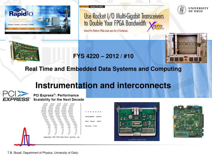
FYS 4220 – 2012 / #10 Real Time and Embedded Data Systems and Computing Instrumentation and interconnects. Embedded / Real-Time systems and the real world. An embedded system must operate and interact with the external world with very high reliability! Processor boards for harsh environment

E N D
FYS 4220 – 2012 / #10Real Time and Embedded Data Systems and ComputingInstrumentation and interconnects
Embedded / Real-Time systems and the real world • An embedded system must operate and interact with the external world with very high reliability! • Processor boards for harsh environment • Special processors, example Digital Signal Processors (DSPs) • Interfaces and interconnects • Bus systems (VME, PCI, CompactPCI, etc) • Serial links, from RS-232 to PCI Exopress, Rapid IO and others • Networks • Topologies of loosely and tigthly coupled distributed Real-time systems • Protocols • Encoding, error detection and recovery • Data transfer software • Standard (serial) I/O • Block I/O, DMA • Asynchronous (non-blocking I/O) FYS 4220 / 9220 - 2012 - Lecture #10
Some examples: Commercial systems and solutions FYS 4220 / 9220 - 2012 - Lecture #10
A digital signal processor (DSP) is a specialized microprocessor with an architecture optimized for the operational needs of digital signal processing. FYS 4220 / 9220 - 2012 - Lecture #10
http://www.measuresoft.com/products/scadapro-server/scada-server.aspxhttp://www.measuresoft.com/products/scadapro-server/scada-server.aspx FYS 4220 / 9220 - 2012 - Lecture #10
Hardware and Instrumentation FYS 4220 / 9220 - 2012 - Lecture #10
Instrumentation • Measuring/control devices and interface to those; • Input instrumentation: measures and/or regulate physical quantities such as flow, temperature, level, pressure, radiation, smoke, angular velocity, etc; • Output instrumentation includes devices such as solenoids, valves, regulators, circuit breakers, relays. Such devices control a desired output variable, and provide either remote or automated control capabilities. These are often referred to as final control elements when controlled remotely or by a control system; • Transmitters are devices that produce an output signal, often in the form of a 4–20 mA electrical current signal, although many other options using voltage, frequency, pressure, or ethernet are possible. This signal can be used for informational purposes, or it can be sent to a PLC, DCS, SCADA system, LabView or other type of computerized controller, where it can be interpreted into readable values and used to control other devices and processes in the system. • More in FYS3230 – Sensors and Measuring technique FYS 4220 / 9220 - 2012 - Lecture #10
Interconnects for the RT- and Embedded World • There are many types of interconnect technologies for Real-Time and embedded systems • The Interconnect market is in constant development, driven by: • Chip and bus technology • Need for higher and higher bandwidths • USB 1.0 : up to 12 Mb/s, USB 2.0 : 480 Mb/s and higher, USB 3.0 : 5 Gb/s • Ethernet IEEE 802.3 (See for instance www.cisco.com) • InfiniBand: communications link for data flow between processors and I/O devices that offers throughput of up to 2.5 gigabytes per second and support for up to 64,000 addressable device • Larger and more complex systems, aeronautics is one example • One of the reasons for the delayed delivery of the Airbus A380 was the very complex (500 km!) cabling for everything from computer controls to in-flight entertainment! • New paradigms: from busses to network based systems. ”Switched fabrics” • Compared to a bussed system a point-to-point link topology has many advantages with respect to: physical distance, scalability, no load dependency, network topology, cost, and more • This is a domain where Real-time, embedded, computer architecture and distributed systems meet and overlap! FYS 4220 / 9220 - 2012 - Lecture #10
Two quick case studies of «convential bus systems: VME and PCI bus • The original VMEbus is a rather old design (based on the MC68K processor bus), but the VME technology is still going strong in the high-end and harsh environment market : • Steadily improved performance • Mechanical robustness • Wide range of modules • However, very expensive • PCI bus is the standard PC peripheral bus • A design for ”plug-and-play” • Whereas VME is a genuine multi-processor bus with possibility for sofisticated bus arbitration, PCI is what the name says: a Peripheral Component Interconnect FYS 4220 / 9220 - 2012 - Lecture #10
VMEbus basics vs. RT / Embedded systems • Architecture: • the VMEbus is a computing system architecture consisting of the electrical specifications for a data bus and the mechanical specifications describing the backplane, bus connector, board sizes and enclosures • developed around 25 years ago by the companies Motorola, Mostek, Signetics and Thomson CSF as a non-proprietary bus • many extensions and improvements over the years, so despite its age, it is still a widely used platform for architecture for real-time systems • VMEbus is a shared system-bus architecture. The system bus resides on a backplane. The backplane has slots, 21 for a full 19-inch VME crate, where processor modules, memory modules or I/O modules connect to the bus • Many vendors provide a wide spectrum of VMEbus modules and components • Applications: • For the professional market, primarily in industrial, military, aerospace, communication and control applications, in particular where robustness is required • VITA • a non-profit organization for real-time and embedded computing systems http://www.vita.com FYS 4220 / 9220 - 2012 - Lecture #10
VMEbus baseline • VMEbus is a multi-processor architecture, although it is often referred to as an instrumentation bus. • The basic architecture is 32 bits, although 64 bit adddressing (A64) and 64 bit data transfer (D64) cycles wwer introduced in the later VME64 revison • The design goal was a backplane bus with high speed and high performance with a powerful interrupt management and multiprocessor capability. The bus is fully parallell with asynchronous protocol • There is a very close relation between the bus structure and the architecture of the MC68K processor family • The theoretical max data transfer rates are given as 0-40 and 0-80 MB/sec for D32 and D64, respectively • Non-standard use of of the VMEbus protocol with an improved backplane has raised the transfer rate to 320 MB/sec and even higher FYS 4220 / 9220 - 2012 - Lecture #10
VME backplane, modules, functionalities • A VME processor module can usually be configured to incorporate all three functions: Controller, Master, Slave FYS 4220 / 9220 - 2012 - Lecture #10
Summary VMEbus general characteristics I FYS 4220 / 9220 - 2012 - Lecture #10
Summary VMEbus general characteristics II FYS 4220 / 9220 - 2012 - Lecture #10
Over to PCI http://www.pcisig.com FYS 4220 / 9220 - 2012 - Lecture #10
PCI bus basics • The PCI bus was orginally developed by Intel. PCI stands for Peripheral Component Interconnect • PCI exists in many flavours: PCI Conventional (i.e. the standard PC card version) 32 bit 33 MHz (max 132 MB/s), 64 bit 33 MHz (max 264 MB/s), 64 bit 66 MHz (max 528 MB/s), PCI Express (PCIe) and Compact PCI • PCI is a synchronous bus where Address and Data are time multiplexed on the same lines • PCI has been through several technical revisions, current PCI Convential is 3.0 • Complete PCI specifications are available from http://www.pcisig.com : the homepage for the PCI Special Interest Group (if you are a member!) FYS 4220 / 9220 - 2012 - Lecture #10
Reflected wave switching • In high-frequency environments such as PCI, convential incident-wawe switching on a terminated bus using drivers with large driving capability would create a number of problems. As such frequencies each trace (bus line) will act as a transmission line, and the electrical characteristics of the trace must also be taken into account when selecting the output driver. • Using strong drivers to switch (by brute force) a bus system at high frequency will present a number of problems, such as: i) very difficult to decouple, ii) spikes, increase EMI (electromagnetic interference) and iv) crosstalk. • The PCI bus is a low power “green” bus, exploiting the reflection of a signal on an unterminated line. The PCI bus is unterminated and uses wavefront reflection to an advantage. A relatively weak output driver drives the signal halfway to the desired logic state, say 1.5V. When the wavefront arrives at the unterminated end of the bus, it is reflected back and doubled (3V)! • The drawback of this method is that the maximum length of a PCI bus can not exceed around 15cm, i.e. for 4 cards. If a longer bus is needed then it must be built from segments interconnected by PCI bridges. FYS 4220 / 9220 - 2012 - Lecture #10
The reflected wave concept requires a fixed and short length of a signal trace, see later. Maximum number of cards on a PCIbus is 4. If more devices are needed, interconnect busses by PCI bridges FYS 4220 / 9220 - 2012 - Lecture #10
Configuration registers • PCI bus is a ”plug and play” system! • This is why you can purchase a PCI card at the local store, plug it into the PC, and activate it by means of the included CD, no jumpers have to be set; • A PCI device is described by the content of its Configuration space; • Each functional PCI device possesses a block of 64 configuration doublewords (32-bit) reserved for its configuration registers; • Configuration registers: see next page. FYS 4220 / 9220 - 2012 - Lecture #10
PCI edge connectors with keying for 3.3 / 5V To prevent stupid users to insert a 3.3V card in a 5V slot FYS 4220 / 9220 - 2012 - Lecture #10
More animals in the PCI Zoo • Common Mezzanine Cards (CMC) and PCI Mezzanine (PMC) standard, uses VME cards as carrier • Compact PCI • PCI Express FYS 4220 / 9220 - 2012 - Lecture #10
Examples of PMCs FYS 4220 / 9220 - 2012 - Lecture #10
CompactPCI applications • CompactPCI is intended as an industrial bus for application in telecommunications, computer telephony, real-time machine control, industrial automation, real-time data acquisition, instrumentation, military systems or any other application requiring high speed computing, modular and robust packaging design, and long term manufacturer's support; • Because of its extremely high bandwidth, the CompactPCI bus is particularly well suited for many high speed data communication applications such as routers, converters and switches. FYS 4220 / 9220 - 2012 - Lecture #10
CompactPCI features • Compared to standard desktop PCI, CompactPCI supports twice as many PCI slots (8 versus 4) and offers a packaging scheme that is much better suited for use in industrial applications. For example, Compact PCI cards are designed for front loading and removal from a card cage. The cards are firmly held in position by their connector, card guides on both sides, and a face plate which solidly screws into the card cage. Cards are mounted vertically allowing for natural or forced air convection for cooling. Finally the pin-and-socket connector of the CompactPCI card is significantly more reliable and has better shock and vibration characteristics than the card edge connector of the standard PCI cards. (Yes, but breaking one pin ruins the whole backplane!) • The power and signal pins on the CompactPCI connector are staged (at insertion power is applied before bus signals) so as to allow hot swapping, a feature that is very important for fault tolerant systems and which is not possible with standard PCI. FYS 4220 / 9220 - 2012 - Lecture #10
CompactPCI backplane FYS 4220 / 9220 - 2012 - Lecture #10
PCI Express, Rapid IO FYS 4220 / 9220 - 2012 - Lecture #10
«Switched (or switching) fabric» • Switching fabric is the combination of hardware and software that moves data coming in to a network node out by the correct port (door) to the next node in the network. • Switching fabric includes the switching units (individual boxes) in a node, the integrated circuits that they contain, and the programming that allows switching paths to be controlled. The switching fabric is independent of the bus technology and infrastructure used to move data between nodes and also separate from the router. The term is sometimes used to mean collectively all switching hardware and software in a network. • The term uses a fabric metaphor to suggest the possible complexity and web-like structure of switching paths and ports within a node. The switching fabric typically includes data buffers and the use of shared memory. • Gigabit Ethernet is a switch based system FYS 4220 / 9220 - 2012 - Lecture #10
Networks and Protocols FYS 4220 / 9220 - 2012 - Lecture #10
Communication between devices • There are three basic device classes – Controllers, Sensors and Actuators. • We need to transfer a information from the sensors to the controller and from the controller to the actuators. • For that, we use some transfer medium (wires, fiber, air..) • And in order to interpret the information, we need a set of protocols Ref. Svein Johannesen, KODE FYS 4220 / 9220 - 2012 - Lecture #10
Why use protocols at all? • Even a “perfect” hardware solution may need some help since: • Almost all communication solutions have frame size limitations • Flow control may be necessary • Communication errors may occur • Source and destination may be on different hardware standards • There are two basic flavors of communications: Peer-to-peer and Master/slave • Peer-to-peer is the democratic “everybody has a right to speak” model • Master/slave is the dictatorial “only speak when spoken to” model • Both models have their uses.. Ref. Svein Johannesen, KODE FYS 4220 / 9220 - 2012 - Lecture #10
The Ethernet connection • Ethernet is used more and more as interconnect in Real-Time systems • High speed and low latency with Gigabit and 10 Gigabit Ethernet • Very cheap, very simple to install • However, a WARNING. The IP (Internet Protocol) does not provide a 100% reliable communication facility as such. There are no acknowledgments either end-to-end or hop-by-hop. There is no error control for data, only a header checksum. No retransmissions. No flowcontrol (RFC 791). • Standard software, protocols TCP/IP and UDP. • The Media Access Control address (MAC address) is a unique identifier assigned to most network adapters. • In VxWorks the basis for intertask communication across a network is a socket. When a socket is created the protocol is specified. • TCP provides reliable, guaranteed, two-way transmission of data with stream sockets. TCP is often referred to as a virtual circuit protocol. • UDP provides a simpler but less robust form of communication. In UDP communications, data is sent between sockets in separate, unconnected, individually addressed packets called datagrams. FYS 4220 / 9220 - 2012 - Lecture #10
Protocols – error detection - encoding • Transmission on external media is subject to interference with possible corruption of data. • Eack packet therefore contains a error detection element, like the CyclicRedundancyCheck in an Ethernet packet. An n-bit CRC, applied to a data block of arbitrary length, will detect any single error burst not longer than n bits (in other words, any single alteration that spans no more than n bits of the data), and will detect a fraction 1 − 2 −n of all longer error bursts. Errors in both data transmission channels and magnetic storage media tend to be distributed non-randomly (i.e. are "bursty"), making CRCs' properties more useful than alternative schemes such as multiple parity checks. • Encoding: • In order to transport digital bits of data across carrier waves, encoding techniques have been developed each with their own pros and cons. • In the well known 8/10 encoding each byte of data is examined and assigned a 10 bit code group. The 10 bit code groups must either contain five ones and five zeros, or four ones and six zeros, or six ones and four zeros. This ensures that not too many consecutive ones and zeros occurs between code groups thereby maintaining clock synchronisation. • In order to maintain a DC balance, a calculation called the Running Disparity calculation is used to try to keep the number of '0's transmitted the same as the number of '1's transmitted. FYS 4220 / 9220 - 2012 - Lecture #10
Tightly coupled systemsA computer architecture domain with relevance for large scale Real-Time systems • In a tightly coupled system the interconnected processors can access a distributed, shared memory • Can be implemented over a common bus, but a bus represents a serious bottleneck: one-at-a-time transfer • An example of a high-speed interconnect standard for shared memory multiprocessing and message passing is IEEE 1596 Scalable Coherent Interface (1995). Scientists at the Institute of Informatics played an important role in specification of SCI. • The goal was to create an interconnect that would scale well, provide system-wide coherency and a simple interface; i.e. a standard to replace buses in multiprocessor systems without the inherent scalability and performance limitations of buses. The working group soon realized that any form of buses would not suffice and came up with the idea of using point-to-point communication in the form of insertion rings as the right way to go. This approach avoids the lumped capacitance, limited physical length/speed of light problems and stub reflections in addition to allowing parallel transactions FYS 4220 / 9220 - 2012 - Lecture #10
SCI basics • The addressing scheme permits up to 65536 nodes. The basic topology is a ring. Request and reply packets are sent in one direction. The node interface checks the destination address of the packet and forwards it when it is not addressed to itself; • Very short latency and high transfer speed made SCI a candidate for CERN/LHC DAQ systems. However, Gigabit Ethernet was in the end chosen as interconnect technology; • SCI made a significant penetration of the market, however, it turned out that it was difficult to compete with Gigabit Ethernet based fabric regarding price; • In a way, SCI was too advanced for its time. Only a few companies made use of the very sofisticated cache coherency mechanism. /* map memory segment on remote node to local memory window and access remote memory as local memory. «ping-pong» latency less than 2 microsec */ remoteBuffer = (volatile unsigned int *)remoteSegmentAddr; /* map */ for (j=0; j<nostores; j++) { remoteBuffer[j] = localBuffer[j]; } FYS 4220 / 9220 - 2012 - Lecture #10