Download
1 / 40
510 likes | 1.02k Views
Superconductivity and Optical fibers. Dr. Ravindra H J & Dr. P.S. Aithal. Objectives. Introduction to Superconductivity, temperature dependence of resistivity Effect of magnetic field, Meissner effect, Type I and Type II superconductors, Temperature dependence of critical field

E N D
Superconductivity and Optical fibers Dr. Ravindra H J & Dr. P.S. Aithal
Objectives • Introduction to Superconductivity, temperature dependence of resistivity • Effect of magnetic field, Meissner effect, Type I and Type II superconductors, Temperature dependence of critical field • BCS theory and High temperature superconductors • Applications of superconductors- superconducting magnet and Maglev vehicles • Fundamentals of Optical Fiber, construction, principle, mechanism of light propagation, acceptance angle, and numerical aperture of optical fibers • Types of optical fibers and attenuation in fibers • Applications of optical fibers
Superconductivity Discovered by – Heike KammerlinghOnnes 1908 Liquefying of gases “ Electrical resistance in some of the metals (lead and mercury) becomes zero at low temperature ( near to absolute zero)” discovered in the year – 1911 Nobel prize - 1913
Drude-Lorentz theory • As the temperature increases more number of electrons are liberated from atoms • If the temperature is decreased then all the electrons will return to atoms.
Matthiessen’s Rule • Total resistivity of the given metal = residual resistivity + resistivity due to lattice vibration
BCS theory - 1957 • Cooper pair – bound pair of electrons formed by the interaction between the electrons with opposite spin and momentum in the phonon filed. • Bardeen • Cooper • Sheiffer
The Meissner Effect • A diamagnetic property exhibited by superconductors. • End result is the exclusion of magnetic field from the interior of a superconductor.
Critical field Critical fields - temperature dependence • The strength of minimum field required to switch a material from superconducting state to normal state Experimentally it is found that Lecture 4
Type I and Type II superconductors Type I (or Soft) Superconductors
Type II (or hard) Superconductors Superconducting region Normal state cores H
High temperature superconductors • copper oxide–based superconductors • Perovskite crystal structure • 1986 publication by Georg Bednorz and K. Alex Müller- superconductivity at 30 K in an oxide of barium, lanthanum, and copper • superconductivity at about 92 K in an oxide of yttrium, barium, and copper (YBa2Cu3O7). • superconductivity at 105 K in an oxide of bismuth, strontium, calcium, and copper. • superconductivity at temperatures as high as 150 K in an oxide containing mercury.
JOSEPHSON EFFECT • JOSEPHSON EFFECT, the flow of electric current, in the form of electron pairs (called Cooper pairs), between two superconducting materials that are separated by an extremely thin insulator. • A steady flow of current through the insulator can be induced by a steady magnetic field. • The current flow is termed Josephson current, and the penetration ("tunneling") of the insulator by the Cooper pairs is known as the Josephson effect. • Named after the British physicist Brian D. Josephson, who predicted its existence in 1962.
SQUIDS - the most sensitive magnetometers • Detection of very weak magnetic fields – 10-14 Tesla • Earth magnetic field ~ 0.5 x10⁻⁴ Tesla Squids – formed by incorporating two Josephson’s Junction in the loop of superconducting materials
Applications of superconductors • Superconducting Magnets • Magnetic levitation and permanent magnets • Wires and cables for motors and power distribution systems • Microwave filters for cellular telephone networks • Superconducting quantum interference device (SQUID) as sensors of heart beats and brain signals, and • Single flux quantum logic in quantum computing system
Introduction to Optical Fibers • Fibers of glass • Usually 120 micrometers in diameter • Used to carry signals in the form of light over distances up to 50-100 km. • No repeaters needed. • Thin strand of metal is called wire • Thin strand of dielectric material is called fiber.
Evolution of Fiber • 1880 – Alexander Graham Bell • 1930 – Patents on tubing • 1950 – Patent for two-layer glass wave-guide • 1960 – Laser first used as light source • 1965 – High loss of light discovered • 1970s – Refining of manufacturing process • 1980s – OF technology becomes backbone of long distance telephone networks in NA.
Advantages of Optical Fiber • Thinner • Less Expensive • Higher Carrying Capacity • Less Signal Degradation& Digital Signals • Light Signals • Non-Flammable • Light Weight
Areas of Application • Telecommunications • Local Area Networks • Cable TV • CCTV • Optical Fiber Sensors
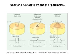
Optical Fiber • Core • Glass or plastic with a higher index of refraction than the cladding • Carries the signal • Cladding • Glass or plastic with a lower index of refraction than the core • Buffer • Protects the fiber from damage and moisture • Jacket • Holds one or more fibers in a cable
Total internal reflection Conditions for total internal reflection : 1. The ray of light must travel from denser medium towards rarer medium. 2. The angle of incidence in the denser medium must be greater than the critical angle for the pair of the media in contact. Snell’s law: n1 sin1=n2 sin2 c = sin-1(n2/n1)
Types of optical fibers Based on refractive index profile: • Step index fiber • Graded index fiber Based on modes of light propagation: Single mode fiber multimode fiber Based on materials: Glass/glass fibers Plastic/plastic fibers Polymer clad silica fiber(pcs)
General classification Three classes of fibers • Single mode step index fiber (SMF) • Multimode step index fiber (MMF) • Graded index multimode fiber (GRIN)
Condition for light propagation • If the medium surrounding the fiber is air then n=1 • i is called wave guide acceptance angle or acceptance cone half angle • Sin i is called numerical aperture (light gathering capacity of the optical fibers
Fractional index change () • r < i • Sin r < sin i • Sin r < NA - The ratio of the refractive index difference between the core and the cladding to the refractive index of core.
Relation between numerical aperture and fractional index change • But , • Since n1=n2
V-number • The number of modes supported for propagation in the fiber is determined by a parameter called V- number • If the medium is air then d – core diameter • - wavelength of the light propagating in the fiber For the medium other than air V- number is For V>>1, the number of modes supported by fiber is given by V2/2
Attenuation in optical fibers • - the loss of power suffered by the optical signal as it propagates through the fiber Attenuation in optical fibers takes through three mechanisms • Absorption losses • Scattering losses • Radiation losses
Absorption losses a) absorption by impurities ( transition metal ions –iron, chromium, copper and cobalt & OH ions b) Intrinsic absorption (self absorption) - absorption due to fiber ( assuming no impurities, no inhomoginities)
Scattering losses a) Rayleigh scattering occurs whenever a light wave travels through a medium having scattering objects whose dimensions are smaller than a wavelength Scattering of photons due to sharp changes in the refractive index Change of refractive index is due to inhomoginities ( occurs during the solidification of fibers) b) Others Defects – gas bubbles, unreacted starting materials And crystallized regions in glass.
Radiation losses a) macroscopic bends b) microscopic bends
Attenuation coefficient • Lambert’s law • The rate of decrease of intensity of light with distance travelled in a homogeneous medium is proportional to the initial intensity • Where is a constant called – attenuation coefficient or attenuation or fiber loss • Integrating above equation we get
Applications of fiber optics • Point to point communication system
Applications • Sensing device Pressure, voltage and current • Data link • Local area network
Advantages • Large band width and can carry large amount of information • Low cost of production • No corrosion and rusting of OF • Superior than metallic cable • No interference of signal between different communication channels • Lightning or sparking tend to cause disturbance in metallic wires and no such disturbance in OF • No requirement of common ground • No energy radiation from a fiber and possibility of information tapping is ruled out. • Due to superior attenuation characteristics transmission of signal to longer distance can be achieved • OF communications systems are simple and cost effective.
Limitations • Splicing is skillful job, requires precission • Difficult to Detect the line break due to accidents – maintenance cost is more • Loss become considerable if the fiber is bent to certain angle. • Fibers undergo thermal expansion due to environmental temperature changes- lead to loss of signal power.
Problems • Calculate the numerical aperture and angle of acceptance for an optical fiber having refractive indices 1.6 and 1.48 for the core and cladding respectively • An optic glass fiber of refractive index 1.5 is to be clad with another glass to ensure total internal reflection that will contain light travelling within 10o of the fiber axis. What maximum index of refraction is allowed for the cladding.