Download
1 / 31
370 likes | 651 Views
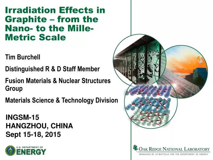
Irradiation Effects in Graphite – from the Nano- to the Mille-Metric Scale. Tim Burchell Distinguished R & D Staff Member Fusion Materials & Nuclear Structures Group Materials Science & Technology Division. INGSM-15 HANGZHOU, CHINA Sept 15-18, 2015. Acknowledgements.

E N D
Irradiation Effects in Graphite – from the Nano- to the Mille-Metric Scale Tim Burchell Distinguished R & D Staff Member Fusion Materials & Nuclear Structures Group Materials Science & Technology Division INGSM-15 HANGZHOU, CHINA Sept 15-18, 2015
Acknowledgements Many colleagues at ORNL and INL, and coworkers in the field of radiation damage and nuclear graphite This work is sponsored by the U.S. Department of Energy, Office of Nuclear Energy Science and Technology under contract DE-AC05-00OR22725 with Oak Ridge National Laboratory, managed by UT-Battelle, LLC. Use of the High Flux Isotope Reactor at the Oak Ridge National Laboratory was supported by the U.S Department of Energy.
OUTLINE Role of Graphite in Nuclear Reactors Mechanism of Irradiation Damage Effects of Irradiation Damage Irradiation Creep Summary and Conclusions
Role of Graphite in a Nuclear Reactor • Neutron moderator • Thermalize fast neutrons to sufficiently low energies that they can efficiently fission 92U235 • Neutron reflector – returns neutrons to the active core • Graphite (nuclear grade) has a low neutron capture cross section • High temperature material • Used in numerous operating reactors (Magnox, AGRs, RBMKs, and HTRs such as HTTR and HTR-10)
Role of Graphite in a Nuclear Reactor (continued) • Graphite is the reactor core structural material • HTGR cores are constructed from graphite blocks • In prismatic cores the graphite fuel elements retain the nuclear fuel • In a pebble bed the graphite reflector structure retains the fuel pebbles • The graphite reflector structure contains vertical penetrations for reactivity control • Reactivity control channels are also contained in prismatic graphite fuel elements
The GT-MHR Utilizes Ceramic Coated Particle Fuel The TRISO fuel particles are formed into 12 mm diameter graphite (carbon) fuel sticks and are inserted into graphite fuel blocks
Graphite Core Components – Pebble Type HTGR (PBMR) • NBG-18 Graphite blocks form the PBMR outer reflector • Reflector penetrations are for the control rods and reserve shutdown system
The Pebble Type HTGR Utilizes Ceramic Coated Particle Fuel The TRISO fuel particles are combined into a graphite (carbon) fuel ball (pebble) 6 cm in diameter
NBG-18 Graphite Microstructure • New nuclear grade • SGL Carbon • Vibrationally molded • Pitch coke filler (1.6 mm max size) • Pore structure characterized using Optical microscopy & automatic Image analysis • X-ray tomography • Hg-intrusion Multiple length scales: nm crystals, µm to mm particles; nm to mm pores
Fine Grain Nuclear Graphite (IG-110) • Fine grain (~20 μm) • High CTE 4-5 x 10⁻⁶ 0C-1 • High strength • isotropic properties and irradiation response High Temperature Test Reactor (Japan), Fuel Blocks and Replaceable Reflector Blocks HTR-10 & HTR-DM, Permanent Core Structure
OUTLINE Role of Graphite in Nuclear Reactors Mechanism of Irradiation Damage Effects of Irradiation Damage Irradiation Creep Summary and Conclusions
Neutron Irradiation Damage GRAPHITE CRYSTAL STRUCTURE • Neutron irradiation causes carbon atom displacement • Dimensional and physical property changes result • Damage mechanism well understood • Key physical properties are: • irradiation dimensional stability, strength, elastic moduli, thermal expansion coefficient, thermalconductivity, radiation creep behavior, fracture behavior, oxidation behavior
The Radiation Damage Mechanism In Graphite CARBON ATOM BINDING ENERGY IN GRAPHITE LATTICE IS 7 eV DISPLACEMENT ENERGY FOR CARBON ATOM IS APPROX. 30 eV
Low Temperature Stored Energy Release • Tirr ~ 30oC • Hanford K • Reactor test • Data • Traditionally associated with Frenkel pair recombination • New evidence? Burchell T, Carbon Materials for Advanced Technologies, Chpt. 13 (1999) p. 429 (Adapted from Nightingale, Nuclear Graphite (1962) )
Displacement Damage in Layered Graphitic Structures • Sequential high resolution transmission electron microscope images illustrating the formation rates of interlayer defects at different temperatures with the same electron irradiation flux & time scale (0 to 220 seconds). (a) 93K, (b) 300K, (c) 573K, in double-wall carbon nanotubes. • The arrows indicate possible interlayer defects. 2 nm Urita, K.; Suenaga, K.; Sugai, T.; Shinohara, H.; Iijima, S. Physical Review Letters2005, 94, 155502.
Displacement Damage in Layered Graphitic Structures • Normalized formation rate of the clusters of I-V pair defects per unit area of bilayer estimated in HRTEM images recorded at different temperatures • The dotted line shows the known temperature for Wigner-energy release (~473 K) • Heggie & Telling, University of Sussex, UK: Simulations of spiro-interstitial Urita, K.; Suenaga, K.; Sugai, T.; Shinohara, H.; Iijima, S. Physical Review Letters2005, 94, 155502.
Radiation Damage In Graphite Is Temperature Dependent INTERSTITIALS Mobile at room temperature. Above ~200oC form into clusters of 2 to 4 interstitials. Above 300oC form new basal planes which continue to grow at temperatures up to 1400oC. VACANCIES Immobile below 300oC. 300-400oC formation of clusters of 2-4 vacancies which diffuse in the basal planes and can be annihilated at crystallite boundaries (function of lattice strain and crystal perfection). Above 650oC formation of vacancy loops. Above 900oC loops induce collapsing vacancy lines.
Basal Planes in Layered Graphitic Structures A high-resolution electron micrograph showing the basal planes of a graphitic nano-particle with an interstitial loop between two basal planes, the ends of the inserted plane are indicated with arrows. Banhart, F. Rep. Prog. Phys.1999, 62, 1181–1221.
OUTLINE Role of Graphite in Nuclear Reactors Mechanism of Irradiation Damage Effects of Irradiation Damage Irradiation Creep Summary and Conclusions
Neutron Irradiation Induced Dimensional Change • Graphite dimensional changes are a result of crystallite dimensional change and graphite texture. • Swelling in c-direction is initially accommodated by aligned microcracks that form on cooling during manufacture. • Therefore, the a-axis shrinkage initially dominates and the bulk graphite exhibits net volume shrinkage. • With further irradiation, incompatibilities in crystallite strains causes the generation of new porosity and the volume shrinkage rate falls eventually reaching zero.
Neutron Irradiation Induced Dimensional Change (continued) • The graphite begins to swell at an increasing rate with increasing damage dose due to c-axis growth and new pore generation. • The graphite thus exhibits volume “turnaround” behavior from initial shrinkage to growth. • Eventually loss of mechanical integrity occurs due to excessive pore/crack generation.
Radiation Induced Volume Changesin H-451 (Effect of Temperature) Interplaner cracks and porosity accommodate thermal expansion and c-axis irradiation induced swelling
Radiation Induced Dimensional Changes in H-451 (Effect of Texture)
Neutron Irradiation Induced Changes in Young’s Modulus • Initial rise due to dislocation pinning • Subsequent increase due to volume shrinkage (densification) • Eventual turnover and reduction due to pore/crack generation and volume expansion • (s/σ0) a (E/E0)1/2 H-451 Graphite
OUTLINE Role of Graphite in Nuclear Reactors Mechanism of Irradiation Damage Effects of Irradiation Damage Irradiation Creep Summary and Conclusions
Radiation Damage in Nuclear Graphite –inelastic deformationIrradiation Induced Creep in Graphite ATR-2E Graphite (WG), Tirr = 550°C, 5 MPa compressive stress ATR-2E Graphite (WG), Tirr = 500°C, 5 MPa tensile stress Graphite dimensional change behavior is modified by the application of stress. Tensile stress hastens turnaround and compressive stress delays turnaround
A Comparison of Compressive and Tensile Creep Strain Behavior for ATR-2E Graphite G. Haag. Report No. Jul-4183, FZ-J Germany Irradiation Temperature =500-550oC
OUTLINE Role of Graphite in Nuclear Reactors Mechanism of Irradiation Damage Effects of Irradiation Damage Irradiation Creep Summary and Conclusions
Summary and Conclusions • > 60 years experience with graphite as a solid moderator • Physics of irradiation damage well understood, but some areas still require a more satisfactory explanation: • Exact nature of irradiation induced defect structures at elevated temperatures • Roles of basal plane and prismatic edge dislocations in the deformation processes • Possible contribution of other dislocation mechanisms (such as dislocation climb/glide) in the creep deformation mechanism. • Interaction of crystal strain with porosity/cracks and the ultimate creation of new porosity & cracks • The application of advanced analytical techniques (HRTEM, SANS) combined with further experimentation (irradiation creep capsules) may provide the explanation we seek • Knowledge and models are required across multi length scales linking the atomic structure to the crystal structure, through the microstructure to the component (nano to macro) and the reactor core behavior.
Knowledge and multiscale models linking to describe complex materials behavior from the sub-nanoscale to the millimetric (component) scale COMPONENTS & STRUCTURES MICROSTRUCTURE CRYSTAL STRUCTURE Finite Element models and large scale simulations ATOMIC STRUCTURE Micro- mechanical models Meso-scale models, diffusion models Electronic structure,MD simulations nm m mm m