Download
1 / 28
310 likes | 631 Views
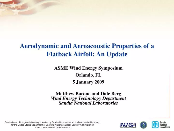
Aerodynamic and Aeroacoustic Properties of a Flatback Airfoil: An Update. ASME Wind Energy Symposium Orlando, FL 5 January 2009 Matthew Barone and Dale Berg Wind Energy Technology Department Sandia National Laboratories. Flatback Airfoils: Background.

E N D
Aerodynamic and Aeroacoustic Properties of a Flatback Airfoil: An Update ASME Wind Energy Symposium Orlando, FL 5 January 2009 Matthew Barone and Dale Berg Wind Energy Technology Department Sandia National Laboratories
Flatback Airfoils: Background • Flatback airfoil shapes have been proposed for the inboard region of wind turbine blades. • Thickness is added about a given camber line – different from “truncated” airfoil. • Benefits • Structural benefit of larger sectional area and larger moment of inertia for a given maximum thickness. • Aerodynamic benefits of larger sectional Clmax , larger lift curve slope, and reduced aerodynamic sensitivity to leading edge soiling. • Drawbacks • Increased drag due to separated base flow. • Introduction of an aerodynamic noise source due to trailing edge vortex shedding. References: C.P. van Dam et al., SAND 2008-2008, SAND 2008-1782, J. Solar Energy Engineering, 2006. 2009 ASME Wind Energy Symposium
Flatback Noise: Is it important? • Flatbacks are used inboard where flow velocities are low • Noise intensity scales with velocity to the fifth or sixth power • Vortex-shedding tone is at low frequencies, 50-250 Hz • Current noise standards emphasize A-weighted noise measurements • A-weighted noise emphasizes the middle of the human hearing range, and de-emphasizes high and low-frequency content However… • Low-frequency noise in the range 20-150 Hz is sometimes addressed by distinct community noise regulations • Tonal noise is often perceived as more annoying than broadband noise; vortex-shedding can generate tones • Low-frequency noise propagates efficiently 2009 ASME Wind Energy Symposium
Goals • Determine aerodynamic properties of a flatback airfoil at Reynolds number typical of inboard region of a utility scale wind turbine blade. • Assess the effect of a simple splitter plate trailing edge attachment on the drag and vortex-shedding noise of a flatback airfoil at this Reynolds number. • Compare aerodynamic predictions using Computational Fluid Dynamics to experimental data for both a sharp trailing edge airfoil and a flatback version of that airfoil • Measure the trailing edge vortex-shedding noise for a flatback airfoil. 2009 ASME Wind Energy Symposium
Wind Tunnel Models Flatback Model • 30% thick DU97-W-300 airfoil • 36-in chord • Steel frame, fiberglass surface • 80 pressure taps per airfoil • Pressure and suction surfaces • 3 Model configurations • 1.7% thick trailing edge (“sharp”) • 10% thick trailing edge (“flatback”) • Flatback with splitter plate • Profiles accurately measured Flatback model with Splitter Plate 2009 ASME Wind Energy Symposium
Instrumentation and Test ConditionsVirginia Tech Stability Wind Tunnel Kevlar Wall • Instrumentation • Surface pressures measured with scanivalve. Lift obtained by integrating surface pressures. • Wake pressures measured with traverse system. Drag determined from wake profiles. • Noise data obtained with 63 microphone phased array • Test Conditions • Clean surface • Tripped boundary layer • 0.5 mm thick zig-zag tape • Three Reynolds numbers • Rec = 1.8, 2.4 & 3.2 X 10⁶ Model in Wind Tunnel Phased Array 2009 ASME Wind Energy Symposium
Location of Microphone Array 2009 ASME Wind Energy Symposium
Experimental Test Program History • Experimental program initiated Autumn 2007 • Wind tunnel testing in the Virginia Tech Stability Wind Tunnel • Test setup and instrumentation described in Berg & Zayas, AIAA-2008-1455 • Challenges encountered in the relatively new test facility • Kevlar walls admit some transpiration mass flow • Solid blockage large relative to previous tests in this facility • Flatback trailing edge vortex-shedding noise frequency below the cutoff frequency of the foam anechoic treatment. • Follow-on Testing Autumn 2008 • Aerodynamics • Limited set of measurements were made with the DU97-W-300 in the solid wall test section • Mass flow vs. pressure drop relationship for the Kevlar walls was measured • Classical linear porous wall interference and blockage corrections applied • In progress: more sophisticated wall corrections based on a panel code, including Kevlar wall deflection • Aeroacoustics • Correction of low-frequency noise measurements was derived 2009 ASME Wind Energy Symposium
DU97-W-300 Lift and Pitching Moment TU Delft data taken in the TU Delft low-speed, low-turbulence wind tunnel. Timmer and van Rooij. J. Solar Energy Engineering, 125:488, 2003. 2009 ASME Wind Energy Symposium
DU97-W-300 Drag 2009 ASME Wind Energy Symposium
DU97-W-300 Pressure Distributions AOA = 4 deg. AOA = 8 deg. 2009 ASME Wind Energy Symposium
DU97-flatback Lift and Pitching Moment • Lift curve slope and maximum lift are increased for the flatback. • Splitter plate results in decrease in lift (not including splitter plate load). 2009 ASME Wind Energy Symposium
DU97-flatback drag • Flatback drag decreases with increasing angle of attack. • Splitter plate reduces the drag by 45-50%. 2009 ASME Wind Energy Symposium
Flatback Acoustic spectra, aoa=4 deg. • Loud tone measured with St = f*h/U = 0.24 . • Splitter plate reduces the peak SPL by 12 dB and shifts the peak frequency higher, to St = 0.30 2009 ASME Wind Energy Symposium
Acoustic Spectra, aoa=11 deg. • At higher aoa: • Tone amplitude decreases by 4 dB . • Effect of splitter plate similar to aoa=4 deg. 2009 ASME Wind Energy Symposium
Acoustic Spectra, tripped b.l. aoa=11 deg. • Tripping increased peak SPL by 4 dB and narrowed the peak. • Splitter plate more effective, reducing the peak SPL by 16 dB. 2009 ASME Wind Energy Symposium
Computational Fluid Dynamics (CFD) Aerodynamic Predictions 2009 ASME Wind Energy Symposium
CFD Method • SACCARA Reynolds-averaged Navier-Stokes finite volume code • Steady solutions using two established turbulence models • Spalart-Allmaras one-equation model (“SA” model) • Menter k-w two-equation model (“k-w” model) • Fine meshes (800 cells along airfoil surface, 240 cells across flatback base, y+ < 0.4) • Boundary layer transition locations calculated using XFOIL and then specified in RANS computations. • Assumption: splitter plate does not influence transition location 2009 ASME Wind Energy Symposium
DU97-W-300 CFD Predictions SA model k-w model 2009 ASME Wind Energy Symposium
DU97-W-300 CFD Predictions Skin friction coefficient k-w model SA model 2009 ASME Wind Energy Symposium
DU97-W-300 Surface Pressure, aoa=4 deg. SA model k-w model 2009 ASME Wind Energy Symposium
DU97-W-300 Surface Pressure, aoa=8 deg. SA model k-w model 2009 ASME Wind Energy Symposium
DU97-W-300 Surface Pressure, aoa=12 deg. SA model k-w model 2009 ASME Wind Energy Symposium
DU97-flatback CFD predictions SA model k-w model 2009 ASME Wind Energy Symposium
DU97-flatback Drag k-w model SA model 2009 ASME Wind Energy Symposium
DU97-flatback with splitter plate SA model 2009 ASME Wind Energy Symposium
Conclusions • Positive impact of flatback shape on lift curve slope and maximum lift maintained at Re = 3 million. • Flatback drag penalties are severe but a simple splitter plate attachment reduced the drag by 45-50% • The present CFD predictions of… • lift give good agreement for both airfoils except near stall. • pitching moment give decent agreement except near stall. • drag are poor, especially for flatback airfoil. • Acoustic measurements of flatback show a loud tone at Strouhal number of 0.24 • Peak SPL is 4 dB lower at aoa=11 deg. than at aoa=4 deg. • Peak SPL is 4 dB higher at aoa=11 deg. for tripped b.l. • Splitter plate reduces peak SPL by 12-16 dB and increases Strouhal number to 0.30. 2009 ASME Wind Energy Symposium
Status and Acknowledgements • Thanks to Prof. William Devenport, Prof. Ricardo Burdisso, and Aurelian Borgoltz at Virginia Tech • A comprehensive report is forthcoming in 2009 detailing: • Aerodynamic and aeroacoustic measurements at lower Reynolds number • Final corrected wind tunnel data using panel code method • Comparisons of aeroacoustic results to trailing edge noise theory 2009 ASME Wind Energy Symposium