Download
1 / 28
280 likes | 296 Views
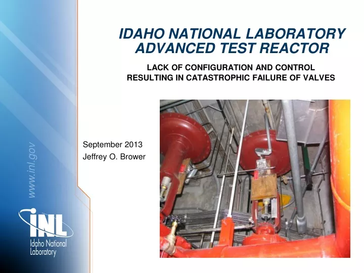
IDAHO NATIONAL LABORATORY Advanced Test Reactor. LACK OF CONFIGURATION AND CONTROL RESULTING IN CATASTROPHIC FAILURE OF VALVES. September 2013 Jeffrey O. Brower. ATR Overview. Reactor Type Pressurized, light-water moderated and cooled, beryllium reflector Maximum Total Core Power – 250MW

E N D
IDAHO NATIONAL LABORATORYAdvanced Test Reactor LACK OF CONFIGURATION AND CONTROL RESULTING IN CATASTROPHIC FAILURE OF VALVES September 2013 Jeffrey O. Brower
ATR Overview • Reactor Type • Pressurized, light-water moderated and cooled, beryllium reflector • Maximum Total Core Power – 250MW • Reactor Coolant • Demineralized water • Coolant Inlet Temperature & Pressure • 125 F (52°C), 355 psi (2450) kPa • ATR has been operating since 1967.
Emergency Firewater Injection System (EFIS) Overview • ATR uses firewater for decay heat removal following selected reactor accidents. • EFIS can be actuated manually, or automatically by low water level or low pressure in the reactor vessel.
Level Control Valves • The ATR EFIS LCVs are safety-related. • Spring-to-open and air-to-close. • Two valves provide dual redundant capability. • Bottom Head EFIS subsystem provides dual redundant capability to the Upper Vessel EFIS subsystem. • Either valve in either subsystem is sufficient to supply adequate cooling water.
Vendor Data • Some vendor data is difficult to read. This was the only information available on the failed valves until the mid 1990’s.
Vendor Data (Continued) • Documentation identifying nameplate data from the valve body and actuator.
Vendor Data (Continued) • Many vendors are no longer in business or have been bought out by other manufacturers. • Many vendors can provide access to catalogs and maintenance manuals for obsolete equipment.
Level Control Valve Known Deficiencies • ATR Operations performs functional testing of these valves every 100 days. • This plot shows the trend as the air pressure was increased prior to 1997 and reduced after 2003.
Level Control Valve Known Deficiencies (Cont.) • LCV-1-7A and LCV-1-7B valve stroke times are marginal • LCV-1-7A and LCV-1-7B valves have leakage past the seats, which allows firewater to leak toward the Primary Coolant System (PCS). • EFIS check valves have leakage past the seats, which allows primary coolant to leak towards the firewater system. • The instrument air supply pressure regulator did not have a conveniently located isolation valve. • The first upstream isolation valve supplies air to about 1/3 of the ATR basements. • The pressure regulator was used as an isolation valve.
Level Control Valve Known Deficiencies (Cont.) • Actual nameplate for the valve with “DIAPH. PRESS RANGE” 0-30 psi • Operators round sheet with supply pressures of 60-80 psi.
Activities Prior to Valve Failure • On March 9, 2011, ATR was completing planned evolutions for a reactor startup for the next operating cycle. Final testing and pre-startup checks were in progress. • Functional testing of the EFIS Level Control Valves was included as a planned evolution. • The EFIS Level Control Valves did not open and close as expected. • Personnel were stationed throughout the plant to operate the valves and observe the evolution. • Engineering and Operations personnel were standing within 6 feet of the valves at the time of failure. • While being observed, the valves appeared to be operating normally, and shut completely.
Valve Failure • While the valves were shut, there was one loud sound, similar to a shotgun blast. • Both valve actuators were jumping around above our heads. • All four valve yokes had failed simultaneously. • The valve actuators were unsupported except for the valve stem, the instrument air tubing, and control power to the solenoid valves.
Valve Failure (Continued) • The yokes failed at a drilled hole in one of the valve yokes, and at the bolt holes in the valve yoke bolting ring.
Valve Failure (Continued) • Fracture at the valve yoke.
Valve Failure (Continued) • Fractures at the bottom of the yoke, where it is bolted to the valve body.
Valve Failure (Continued) • Rust that had developed in the pre-existing cracks in the yoke bolting ring.
Valve Failure (Continued) • Finite element models were developed to determine potential failure locations. • The initial failure point was never positively identified, but was either the drilled hole on the yoke or the cracked bolt holes.
Valve Failure (Continued) • Simple calculations were performed to determine if the available air pressure could have failed the valve yoke. • Instrument air system pressure is 125 psig. • The actuator diaphragm is 250 in2 with an effective area of 300 in2. • Effective applied force = 125 psig X 300 in2 = 37,500 lb • Yoke cross section ≈ 2.3 in2 / yoke • Yoke load = 37,500 lb / 2.3 in2 = 16,300 psi • Allowable load for ASTM A126 Grade B = 31,000 psi • The yoke should not have failed at these loadings. • The more likely failure location was at the pre-existing flaws on the bolting ring - pre-existing cracks with oxidation (rust).
Spare Parts • Spare valve body in the warehouse.
Spare Parts (Continued) • Disc in the spare valve body.
Spare Parts (Continued) • Disc in the failed valves was a different design than the disc in the spare valve body. • Make sure you have the correct spare parts.
Pressure Regulator and Lack of an Isolation Valve and Overpressure Protection • Compressed air and backup nitrogen control panel before modification.
Pressure Regulator and Lack of an Isolation Valve and Overpressure Protection (Continued) • Same compressed air and backup nitrogen control panel with a new isolation valve, check valves, pressure regulators, and overpressure protection.
Control Room Switch Positions • Manual control switches for the level control valves had no labels. • Open/Close • Manual/Auto • Normal/Reset
Control Room Switch Positions (Continued) • Control switches can only be used to manually trip the valve open. • Switches cannot be used to shut the valves unless the automatic trip signals have cleared.
Extent of Conditions • All air operated valves at ATR were walked down to ensure another valve failure similar to this one would not occur. Approximate 325 valves were walked down and evaluated for potential failure concerns. None of the other valves were safety related valves subject to similar mechanisms. • All other safety related valves were previously designed, installed, and maintained to prevent failure at instrument air system pressure. • No other air valves were replaced or modified as a result of the valve failure or extent of condition evaluation.
Valve Replacement • Replacement Velan triple offset butterfly valves arrived at the INL one week after the failure. They had been ordered 30 months earlier. Removal of the failed valves and installation of the new valves was a material handling challenge.
Questions? Lessons Learned • How good is configuration control at your facility? • Does your facility have as-built drawings? • Does your facility have sufficient spare parts? Do you have any critical spare parts? Are your spare parts correct for the installed equipment? • Do you have air operated components that can be overpressurized?