Download
1 / 19
240 likes | 612 Views
PS2 Keyboard Interface Using Spartan-3 Starter Kit Board. Structure of Computer Systems Brateanu Vlad Group 30442. Introduction. PS2 port was introduced in IBM’s Personal System 2 personnel computers.

E N D
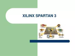
PS2 Keyboard Interface Using Spartan-3Starter Kit Board Structure of Computer Systems Brateanu Vlad Group 30442
Introduction • PS2 port was introduced in IBM’s Personal System 2 personnel computers. • It is a widelysupported interface for a keyboard and mouse to communicate with the host.
The PS2 Connector • The PS2 port contains two wires • for communication purposes. • One wire is for data, which is • transmittedin a serial stream. • The other wire is for the clock information, which specifies when thedata is valid and can be retrieved.
Timing Diagram • Information is sent via 11-bit Words. • Each word contains a Start bit, 8 Data bits, a Parity bit and a Stop bit. • The keyboard interface allows for bidirectional data transfer.
Design – The 7 Segment DIsplay • The Four Digit 7 Segment will be used for displaying the result, which will be the SCAN code coresponding to the pressed key • Since the scan code of each button is formed of 8 bits, the value will be displayed in hexadecimal using 2 seven segment displays
Design – The Interpreter • It has the job of Interpreting the 8 bit character received by the PS2 Controller. • It checks to see if received data is either a character, or a Caps Lock or Num Lock command. • In case of the latter, it also sends the required signal back to the PS2 Controllerso that it may inform the Keyboard that the coresponding LED should be switched on.
Design – The PS2 Controller • Is made up of two Finite State Machines. • One for the reading operation and the other for the Writing operation. • While a writing operation occurs, the read is blocked.
PS2 Controller Read Operation • The falling edge of the PS2_CLOCK signal is used as refference for data retrieval. • At each falling edge, another bit is loaded into a shift register. • After all bits are loaded, the Char_Ready signal is asserted and the Interpreter may read the whole character
PS2 Controller Write Operation • The keyboard sends data only when both the data and clock lines are High (the idle state) • The host is the buss master, meaning that before sending data, the keyboard must first check if the host isn’t already sending data.
PS2 Controller Write Operation (2) • Same as for the Read operation, this time, the keyboard is the receiver. • The host drives the clock signal low, then sends an “ED” (in hexadecimal) command to which the keyboard replies with “FA” as acknowledgement. • After this, the host sends another byte to set led status.
Bibliography • [1] Spartan 3 StarterKit Board User Guide -for basic information • [2] FPGA Prototyping by VHDL Examples – Xilinx Spartan 3 Version by Pong P. Chu Cleaveland State University - Chapters 8 and 9 describe in detail the operations and also gives examples