Download
1 / 19
190 likes | 365 Views
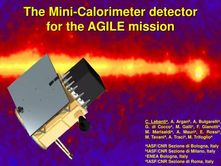
The Mini-Calorimeter detector for the AGILE mission. C. Labanti a , A. Argan b , A. Bulgarelli a , G. di Cocco a , M. Galli c , F. Gianotti a , M. Marisaldi a , A. Mauri a , E. Rossi a , M. Tavani d , A. Traci a , M. Trifoglio a

E N D
The Mini-Calorimeter detector for the AGILE mission C. Labantia, A. Arganb, A. Bulgarellia, G. di Coccoa, M. Gallic, F. Gianottia, M. Marisaldia, A. Mauria, E. Rossia, M. Tavanid, A. Tracia, M. Trifoglioa aIASF/CNR Sezione di Bologna, Italy bIASF/CNR Sezione di Milano, Italy cENEA Bologna, Italy dIASF/CNR Sezione di Roma, Italy
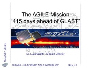
AGILEAstrorivelatore Gamma ad Immagini LEggero(Light Gamma-ray Imager for Astrophysics) The AGILE Mission combines, for the first time in high-energy astrophysics a wide field-of-view instrument sensitive in the 30 MeV - 50 GeV band, with a 10-40 keV X-ray monitor. It will explore a wide variety of celestial phenomena including active galactic nuclei (AGNs), gamma-ray bursts (GRBs), diffuse emission, pulsars, and other Galactic sources. Mass: 190 kg (120 kg payload) Power 135 W (46 W payload) Launch: Autumn 2005 Orbit: Equatorial at ~ 560 km Mission lifetime: 3 years minimun AGILE is a small mission of the Italian Space Agency (ASI), the involved institute are: IASF-CNR INAF, Milano Univ. di Trieste and INFN CIFS IASF-CNR INAF, Roma IASF-CNR INAF, Bologna Univ. Roma 2 and INFN Univ. Roma 1 and INFN ENEA Roma ENEA Bologna Homepage: http://agile.mi.iasf.cnr.it/
AGILE Integrated Payload Anticoincidence Super Agile (10 – 40 keV) P/L Detector Silicon Tracker SystemHarness & Heaters GRID(30 MeV – 50 GeV) Minicalorimeter(.3 – 200 MeV) P/L Data Handling Unit P/L Shell P/L Power Supply Unit Star Sensors Units GPS Units Courtesy of AST
Instrument Performance AGILE-GRID En. range ~ 30 MeV- 50 GeV Aeff (400 MeV, 0º) ~570 cm2 FOV ~ 3 sr PSF (400 MeV, 0º) ~1.22º Source Loc. Acc. ~ 5' - 20' DE/E ~ 1 Deadtime < 200 msec Super--AGILE En. range ~ 10- 40 keV Aeff (13.1 keV, 0º) ~ 80 cm2 FOV ~ 0.8 sr PSF (pixel size) ~ 6' Source Loc. Acc. ~ 1' - 3' DE < 4 keV Deadtime ~ 5 msec Minicalorimeter En. range ~ 0.3- 200 MeV DE ~ 1 MeV Aeff (1- 10 MeV, 0º) ~500 cm2 Deadtime ~ 5 msec
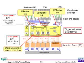
MCAL on AGILE • TASK • In the GRID operation mode, supply energy and position informations on the particles detected by the Tracker. • In the BURST operation mode supply time and energy informations of impulsive gamma events. • Continuolsly supply the background behaviour via ratemeters in variuos energy ranges • ARCHITECTURE • MCAL is made of 30 CsI(Tl) scintillator bars. • The bars are arranged in two layer of 15 elements orthogonal to each other • Each bar is optically coupled to 2 Photodiodes (PD). • The signals of each bar are feed to the GRID and BURST chain where they are analysed at the same time
MCAL Bar detectors • 2 custom PIN PD for each bar (Si active area 256 mm2, 130 pF, Il 1.5 nA @ 20 °C) • CsI(Tl) scintillator 375 23 15 mm • The scintillation light collected by one PD depends from the interaction position x and the energy deposited E I E*exp(-x) in the range 0.0020.045 cm-1 depending from surface treatment and wrapping • Weighting the signals A end B from the two PD of one bar the energy and position can be evaluated x ln (A/B) E sqrt(A*B)
Flight bar design The bars with PD glued, wrapping etc. are hoisted in a carbon fibre structure to give modularity and strenght. Two prototype bars have been tested in the MCAL temperature ranges (operative, non-operative etc).
Plane of the signals from PDs Test with a collimated 22Na source (511 and 1275 keV) 1 cm from PD A 18.75 cm from PD A 36.5 cm from PD A
Energy and position evaluation Energy reconstruction Position reconstruction Collimated 22Na spectra collected by one PD for different source positions.
Energy and position resolution All parameters evaluated with pre-amps shoving ~ 850 e- rm noise at room Temp.
MCAL operative modes • GRID: MCAL is ‘slave’ of the Tracker. On command all the PD signals are stretched, AD converted and sent to the Data Handling. Operative range for each bar is 1 500 MeV. MCAL can start a GRID event if it detects more than 50 MeV on the whole system. The FEE can handle an event rate up to 1300 Hz. • BURST: MCAL indipendently detects events in the range 250 keV e 250 MeV. The AD converted data are processed in the Data Handling for transient event search. The FEE can handle an event rate up to 500 kHz. MCAL FEE deals, at the same time, the processing of the two modes as well as the generation of House_Keeping data, Telecommands implementation etc.
MCAL FEE • Overall power consumption: 5 W • PD’ s charge preamplifiers: ~ 850 e- rms • GRID, BURST, HK & TC functions contained in two boards with the same footprint of the bar assembly Simplified Engeneering Model of MCAL DFEE Each board includes the analogue chains for 15 bars. The circuits for GRID operations up to A/D conversion are contained in one board, the BURST operations are all developed in the other board.
Optical cable VME Crate Science Console Host Computer MCAL SEM 8 bars DFEE SEM … … B U r s t GRID HK T C Br i dge MCAL Test Equipment A dedicated Test Equipment has been realized for SEM MCAL test The system is based on a VME bus with a board for each MCAL I/F (GRID, BURST, HK-TC)
Set-up misure CERN Lato B Tracker P4 P3 P2 P1 MCAL Lato B Beam 5 6 Strip 1 Lato A 7 1 8 2 Strip 384 3 4 Lato A variable 18 mm Test with particles MCAL SEM (with early prototype bar detectors) has been tested both in laboratory and, togheter with a prototype Tracker and AC, with particle beam (CERN T-9 and T-11)
Test with particles Energy lost bymof 2 GeV/c impinging on MCAL with various angle Difference between the position of interaction ofmimpinging on one MCAL bar evaluated with the PD data and with the projection of the position evaluated in the Tracker.
Conclusions AGILE will be launched at the end of 2005 The prototype studies on MCAL detector and electronics have demonstated the validity of the choosen design