Download

1 / 13
130 likes | 228 Views
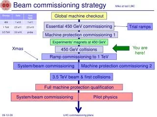
Beam Commissioning Workshop , 19th January 2010. Luminosity Optimization. S. White, H. Burkhardt. IR Layout and Bumps. MCBX in triplet - important for crossing angle and aperture at injection. Act on both beams and planes at the same time. MCBC and MCBY only for one beam allow

E N D
Beam Commissioning Workshop, 19th January 2010 Luminosity Optimization S. White, H. Burkhardt
IR Layout and Bumps • MCBX in triplet - important for crossing • angle and aperture at injection. Act on both • beams and planes at the same time. • MCBC and MCBY only for one beam allow • to drive the beams independently. • A bump including MCBX magnets will either • separate or bring the beams together. • An offset of the IP can only be corrected with • MCBC and MCBY. • Example of an IP bump with and without MCBX: • Creates a large offset in the TCT region. • This offset can be reduced by using MCBX. • MCBC and MCBY bumps are not suited for large corrections. • They should only be used for fine tuning. • A large transverse offset of the IP should be corrected by different • means (global correction).
Machine Protection • An orbit offset at the TCT can comprise the collimators efficiency to protect the triplets. In order • to correctly shadow the triplets the two following conditions should be fulfilled: Worst case scenario: b* = 2 m at IP5. For a half gap of 12.8 s at the TCT: Dxmax~ 1.2 s with separation bump on and ~1.8 s with separation off. 1 s for collimators operation → 0.8 s is left for optimization. • There should be enough space for optimization. • Solutions to be discussed for wider scans. • Increasing b*would increase the allowed • scan range, but requires larger bumps. • These bumps should be tested with safe beam • in order to avoid any unpredicted limitations. • Set limits according to simulations and • measurements in the steering software. • If the allowed scan range is not sufficient this • can be overcome by moving the two beams. IP5 : margin of at least 4s in vertical and 5.5s in horizontal. Numbers are similar or better for other IPs.
Corrections Using BPM measurements • Residual separation before corrections. Large offsets were observedin some cases. • Correcting the offsets to align beams based on BPM measurements with local closed orbit bumps • was sufficient to establish collisions at the four IPs. • This might not be the case for higher energies/smaller beams → at 3.5TeV. Van Der Meer scans could • be necessary to find the beams. • Special case of IP1 and IP5: • Button pick-ups with higher resolution were installed in IP5 and IP1 which directly measure the separation • in Q1. • Not used in 2009 (only BPMSW) → we could possibly reach a better alignment using these. • Implement a display in the software.
Status after Corrections • (Large) IP transverse offset remaining. Difficult to correct using • closed orbit bumps because of aperture limitations. • Largest measured crossing angle ~40 murad. Luminosity reduction • negligible. • IP2/IP8 smaller offsets : MCBX magnets were not used. • IP5 some magnets were not commissioned: injection separation bumps • magnets were used as a temporary solution. • The actual settings are not optimized in terms of IP position and aperture. • Re-optimize all IPs starting from a “cleaner” situation and reset collimators afterwards.
Luminosity Optimization Principle Luminosity and evolution as a function of the separation for equal Gaussian beams. • Transverse separation scans allow to find an optimum and give a measurement of the beam • sizes at the IP. Run ‘09 • Mini-scans were performed in all IPs during STABLE BEAMS. • All scans done manually with 3 points for a range of +/- 1 s. • ~40 minutes per IP due to the very low rates. • The software interlock system limits the changes in strength in the orbit correctors. • Default settings were too tight → had to be manually released to allow for scans of +/- 1s. • Could go up to +/- 2s by moving the two beams.
First Results (LHCb) Final point after 2nd scan HOR: Beam 2 shifted +1/2s Initial rel. position before all scans HOR: Beam 1 shifted -1/2s VER: Beam 1 shifted +1s VER: Beam 2 shifted +1s Initial rel. position before all scans Courtesy of R. Jacobsson • Measurements done in LHCb. Because of limited scan range several iterations were necessary to find • the peak and reach the optimum settings. Gain of ~ 40% overall.
First Results (CMS) Courtesy of T. Camporesi • Measurements done in CMS. Because of limited scan range several iterations were necessary to find • the peak and reach the optimum settings. Gain of a factor ~2 overall.
First Results (ATLAS) (A. U.) (A. U.) (A. U.) (A. U.) Courtesy of W. Kozanecki • Measurements done in ATLAS only one set of scans was performed that shown no clear evidence • for misalignments. Results were similar for ALICE.
Software and Data Exchange • The same software was used for IR steering and to perform the mini-scans. • Screen shots of the panels • used for IR steering and • luminosity scans. • Here is an example of a • scan performed in LHCb. • The data exchange with the experiments was done via DIP and was rather successful. • Fully automated scans routine are implemented and were tested during the dry runs. • Single beam knobs generated with online model for all IPs/beams/planes. Template script available: can • easily be generated for any optics. • To be implemented: • Database access (work in progress will be ready for start-up). • Ability to drive both beams at once (implement knobs and script for online model). • Improved online analysis tools.
Lessons and Possible Improvements • Duration of a scan: • Very low rates → step trough the different separations manually in order to allow the experiments • to collect enough statistics : several minutes per point for a total duration of ~20 minutes per plane. • Move on to a fully automated procedure. • Once we have higher rates the limitation will come from the magnet ramping rates. • Online analysis: • No detailed analysis provided online → had to wait for the experiments feedback. • Improve online analysis tools → the operator should be able to perform a scan and re-align the beams • without feedback from the experiments. • Scan range: • Limited by the software interlock system. Proved to be a real limitation when the peak was out of reach. • CMS and LHCb needed several iterations before the optimum could be found. • Allow for +/- 2s scan range by default. • If necessary scan with both beams to minimize offset at the TCT (will also optimize ramping time). • Avoid using MCBX (larger hysteresis).
Luminosity Calibration • The Van Der Meer scan method can also be used to determine the absolute luminosity by measuring • the beam sizes at the IP. All experiments requested an absolute luminosity calibration. • Calibration scans have different requirements in order to reduce the systematics: • Specific measurement → done on request. • Detailed scan : more points to reduce fit errors and wider range to measure full profile. +/- 5s should • be sufficient (learn with experience). • Move only one beam. • Bunch-by-bunch acquisition and analysis. • No crossing angle and moderate intensity (5e10 p/bunch). • Can only be done once we have higher statistics and stable optics/beam conditions. • Once statistic are no longer a limitation a scan is expected to last a few minutes. • Proposal for the upcoming run: • Beam parameters are not too far from what is required for the calibration scans → use the end of fills. • A calibration of the length scale using the beam spot measurements from the experiments could further • reduce the uncertainty on the position → dedicated scans with longer steps. • The procedure and tools are the same as for optimization scans (tested and ready).
Summary • IR Steering: • Test bumps for aperture limitations. • Generate MCBX knobs for all IPs in case large corrections are necessary. • Re-align all IPs optimizing aperture and IP transverse position. • Machine Protection: • Could become a limitation for squeezed optics → to be studied in details together with the • collimation team. • Luminosity Optimization: • Luminosity optimization using the Van Der Meer method was successfully performed in all IPs. • The software and data exchange procedure are operational. • Move on to a fully automated procedure to allow for optimization as a part of routine operation. • Luminosity Calibration: • Done on request by the experiments. • Optimum beam parameters to be determined (learn with experience).