Download
1 / 14
140 likes | 256 Views
DC FEE FDR. C. Pancake - Chief Engineer T.K.Hemmick - Coordinating Physicist J. Velkovska V. Pantuev. Outline. Geometrical Description: Where does the DC lie in PHENIX? Pictorial Guide through the Prototype. Physics-driven Design Parameters Position Resolution. Time resolution.

E N D
DC FEE FDR C. Pancake - Chief Engineer T.K.Hemmick - Coordinating Physicist J. Velkovska V. Pantuev
Outline • Geometrical Description: • Where does the DC lie in PHENIX? • Pictorial Guide through the Prototype. • Physics-driven Design Parameters • Position Resolution. • Time resolution. • Device/system-driven Design Parameters • Keystone layout. • Number of Channels. • Performance of ASD8 prototype “on-chamber” • Real running threshold. • Summary
Geometrical Description • The Drift Chambers are the innermost detectors mounted on the PHENIX Carriages. • They are shaped as a cylindrical section which: • subtends a 90 degree azimuthal opening • is 40 cm thick • is 2 meters long (along the collision axis).
Drift Chamber Frame • Each Drift Chamber consists of a single continuous gas volume of 50-50 Ar-ethane. • Particles enter and exit through Mylar widows in the front and back. • The other sides are composed of welded titanium arcs and end-beams • Both the arcs and end-beams are braced by gussets which span the opening of the “C-channel”.
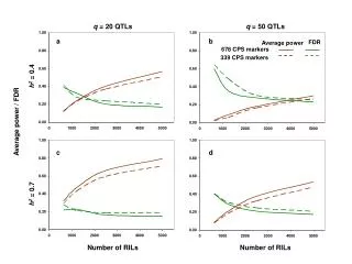
Design goals 1 The Drift Chamber serves as the principle device in determining the momentum resolution of PHENIX. Shown above are early calculations of the momentum and mass resolution of the system assuming 150 micron position resolution. We are dominated by multiple scattering for the most important range of momenta (~1/2 mf) so 150 microns is a conservative figure. With a drift velocity of 50 microns/nsec, time bin resolution of 1 nsec of better (0.8nsec used) is sufficient from the electronics.
Design Goals 2 The occupancy of the drift chamber is roughly 1 particle per wire per central Au+Au collision (i.e. 100%) Using Multi-hit electronics we effectively create an occupancy of 1 particle per “single-particle-dead-time” where single-particle-dead-time relates to the ability of the electronics to separate two close signals. The design goal (to get <10% occ) is 1.5mm (30 nsec) effective width. The 6nsec shaping of the ASD8 and the 12.8 nsec time bucket of the TMC fall conservatively below these criteria.
On-Chamber Tests V. Pantuev, E. Vznouzdaev • Since mid-December, the wire sections of the prototype have been operating well and numerous tests have been done using older “analog-section only” boards. • In these tests, 5-6 fC running thresholds were found to produce performance in excess of all design parameters over a range of operating voltages. • Without operating wires, the one card of the full (ASD/TMC) electronics system was put on chamber and shown (after some grounding) to operate well with typically 5 fC thresholds and for best channels at 3 fC thresholds.
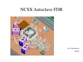
Shown in the figure above is the “large-scale” prototype. This chamber has full dimension for length and depth. It only covers a 15 degree azimuth (full chamber = 90 degrees). The large-scale prototype has two end beams and three sections called “keystones”. The full-sized chamber will have 20 keystones per side. “Gussets” divide the arc into “Keystones”.
Functional Description This figure shows the distribution of HV and signal wires for a single keystone as viewed from the end. Each keystone contains 6 cages called (from smallest to largest radius) X1 (12-wires), U1(4-wires), V1, X2, U2, V2. 4 Electronics cards (ASD8-TMC) supporting 40 channels each are housed in the keystone. These 4 cards are read into one FEM which communicates with the DAQ.
Low Voltage Due to the exceptional sensitivity of the DC electronics (3-5 fC thresholds), we have chosen to place DC-DC convertors in every keystone. Each set of three convertors will be supplied with its own twisted pair DC input supply. The power budget for one keystone is shown in the table below (numbers for the FEM card are ONLY an educated guess).
Cooling Shown in the figure above is the physical configuration of the ASDTMC cards and the FEM within one keystone. The total heat budget for this section is <100 Watts dominated by the TMCs. We have calculated that if the TMC chip were thermally connected to the Shield wing that the temp rise assuming conduction only would be at most 13 degrees C.
Cooling 2 Since the shield wing also serves to shielding the analog from the digital sections, we must predicate its design on the dual constraints of heat removal and EM radiation shielding. The EM radiation tests with real FEM cards are ongoing. We calculate that reasonable flow velocity (25 ml/sec) in each of 4 3/8” pipes pipes on one chamber will easily remove the heat. Room exists for cooling lines, but the final design awaits proof that noise and heat needs can be addressed with a single solution. Air flow has been tested as insufficient.
Summary • System minimum requirements and the design value are listed below: • Better than 150 micron resolution (3 nsec). • 0.8 nsec least count (chamber limited). • Better than 1.5 mm (30 nsec) recovery. • Typically 10 nsec to sharp input (chamber limited). • Thresholds of 5 fC or lower. • Achieved 3 on best channels better than 5 on all of previous cut of ASD board. Tests of full system underway. • Cooling is still an issue of concern (Hemmick’s fault) and will soon be addressed in detail. • Chamber tests of the analog section-only were extensive and show excellent performance. • Chamber tests of the full chain are ongoing. • We will order next round of boards (enough for prototype in engineering run) after seeing first indication of continued good performance on the prototype with the full system.