Download
1 / 78
780 likes | 799 Views
Learn about the various models and techniques used in computer graphics illumination and shading, including empirical and physically-based models. Understand the importance of light sources and surface properties in creating realistic shading effects.

E N D
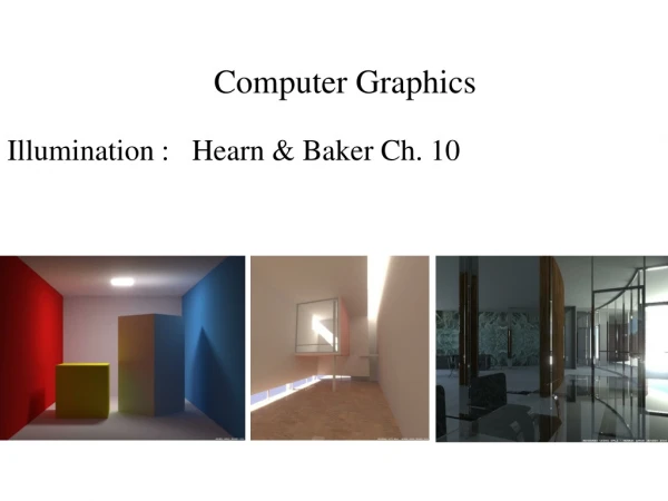
Computer Graphics Illumination : Hearn & Baker Ch. 10
Illumination Models Illumination: transport of energy from light sources to surfaces and points via direct & indirect paths. Lighting: computing intensity reflected from 3D point in scene. Shading: assigning pixel colours colour. Illumination Models: • Empirical: simple approximations to observed phenomena. • Physically-based: model actual physics of light interactions.
Two Components of Illumination • Light sources • Surface properties • Light sources (or emitters) • Spectrum of emittance (i.e., color of the light) • Geometric attributes • Position • Direction • Shape • Directional attenuation • Polarization
Surface properties • Reflectance spectrum (i.e., color of the surface) • Subsurface reflectance • Geometric attributes • Position • Orientation • Micro-structure
Why we need shading • Suppose we build a model of a sphere using many polygons and color it with glColor. We get something like • But we want
Shading • Why does the image of a real sphere look like • Light-material interactions cause each point to have a different color or shade • Need to consider • Light sources • Material properties • Location of viewer • Surface orientation
Scattering • Light strikes A • Some scattered • Some absorbed • Some of scattered light strikes B • Some scattered • Some absorbed • Some of this scattered light strikes A and so on
Rendering Equation • The infinite scattering and absorption of light can be described by the rendering equation • Cannotbesolved in general • Ray tracing is a special case for perfectly reflecting surfaces • Rendering equation is global and includes • Shadows • Multiple scattering from object to object
Global Effects shadow multiple reflection translucent surface
Local vs Global Rendering • Correct shading requires a global calculation involving all objects and light sources • Incompatible with pipeline model which shades each polygon independently (local rendering) • However, in computer graphics, especially real time graphics, we are happy if things simply “look right” • Many techniques approximate global effects
Light-Material Interaction • Light that strikes an object is partially absorbed and partially scattered (reflected) • The amount reflected determines the color and brightness of the object • A red surface appears red under white light because the red component of the light is reflected and the rest is absorbed • The reflected light is scattered in a manner that depends on the smoothness and orientation of the surface
Light Sources General light sources are difficult to work with because we must integrate light coming from all points on the source
Simple Light Sources • Point source • Model with position and color • Distant source = infinite distance away (parallel) • Spotlight • Restrict light from ideal point source • Ambient light • Same amount of light everywhere in scene • Can model contribution of many sources and reflecting surfaces
Infinitely Distant Light Sources • Example: sunlight
attenuation for rays at angle f from the cone axis al is the attenuation exponent.
Other Light Sources • Spotlights • Point source whose intensity falls off away from a given direction • Requires a color, a point, a direction, parameters controlling the rate of fall off • Area Light Sources • Light source occupies a 2-D area (usually a polygon or disk) • Generates soft shadows • Extended Light Sources • Spherical Light Source • Generates soft shadows • Warn lighting models • Create studio lighting effects using sets of point emitters and parameters to simulate flaps, etc.
“Standard” Lighting Model • Three terms linearly combined: • Diffuse component for the amount of incoming light reflected equally in all directions • Specular component for the amount of light reflected in a mirror-like fashion • Ambient term to approximate light arriving via other surfaces
Ideal diffuse reflection • An ideal diffuse reflector, at the microscopic level is a very rough surface • Because of these microscopic variations, an incoming ray of light is equally likely to be reflected in any direction over the hemisphere: • What does the reflected intensity depend on? • angle of incident light
Ideal diffuse reflector : Lambertian reflector For a Lambertian surface we can set a parameter kd that determines the fraction of the incident light that is scattered as diffuse reflection kd is the diffuse-reflection coefficient or diffuse reflectivity • To simulate a highly reflective surface set the value near 1 • To simulate a light absorbing surface set the value near 0
Ambient & diffuse reflection for single point-source illumination unit direction vector to light source
Ideal Reflector • Normal is determined by local orientation • Angle of incidence i = angle of reflection r • The three vectors must be coplanar r = 2 (l· n ) n - l
2(N.L)N L N L R q qi q qr qi=qr R = 2(L.N)N - L
The specular reflection range is specified by an exponent. Shiny surface - large specular-reflection exponent, ns, means a narrow specular reflection range -- more like a mirror, with reflections seen close to the reflection angle. ns is infinite for a perfect mirror; for a rough surface it is assigned a value near 1 For a perfect mirror the reflection would only be seen where viewing angle f is zero, measured relative to the specular reflection direction R
Intensity of Specular Reflection depends on surface material properties and angle of incidence (and other factors, e.g. colour): These can be expressed as coefficients W(), whose values can be found experimentally Using these coefficients and Fresnel's Laws of Reflection we can write the Phong specular reflection model as cos can be found as the dot product V.R And assuming the specular reflection coefficient is constant for any surface, ks, we obtain the following expression
This gives us the popular Phong model for calculating specular reflection intensities
The Shininess Coefficient ns • Values between 100 and 200 correspond to metals • Values between 5 and 10 give surface that look like plastic n=0.1 n=0.5 n=1 n=2 n=10
Phong Lighting • The most common lighting model in computer graphics: v • The nshiny term is a purelyempirical constant that varies the rate of falloff • Though this model has no physical basis, it works (sort of) in practice
Specular Reflection (Phong Model) L V R • Incoming light is reflected primarily in the mirror direction, R • Perceived intensity depends on the relationship between the viewing direction, V, and the mirror direction • Bright spot is called a specularity • Intensity controlled by: • The specular reflectance coefficient, ks • The parameter, n, controls the apparent size of the specularity • Higher n, smaller highlight
Modified Phong Model • The specular term in the Phong model is problematic because it requires the calculation of a new reflection vector and view vector for each vertex • Blinn suggested that an approximation using the halfway vector is more efficient
Specular Reflection Speedup L V H N • Compute based on normal vector and “halfway” vector, H • Easier to compute than mirror direction • Similar result R is not shown, RV
Using the halfway angle • Replace (v· r )a by (n· h )b • bis chosen to match shinyness • Note that halfway angle is half of angle between r and v if vectors are coplanar • Resulting model is known as the modified Phong or Blinn lighting model • Specified in OpenGL standard
Example Only differences in these teapots are the parameters in the modified Phong model
Putting It Together • Global ambient intensity, Ia: • Gross approximation to light bouncing around of all other surfaces • Modulated by ambient reflectance ka • Just sum all the terms • If there are multiple lights, sum contributions from each light • Several variations, and approximations …