Download
1 / 15
150 likes | 154 Views
This study focuses on X-ray diffraction analysis of various irradiated materials, including graphite polymorphs, h-BN, Be, AlBeMet, tungsten, molybdenum, Glidcop, Mo-Gr, Cu-CD, carbon fiber composites, and superalloys (Ti6Al4V, s-INVAR, and gum metal). The irradiation methods include 118-200 MeV protons at BNL BLIP, fast neutrons at BNL BLIP, 28 MeV protons at Tandem, and neutrons at Tandem. The study also involves localized damage followed by EDXRD studies and the development of a multi-functional stage for handling real-size irradiated specimens. The goal is to understand the effects of irradiation and post-irradiation annealing on the crystal structure and lattice parameters.

E N D
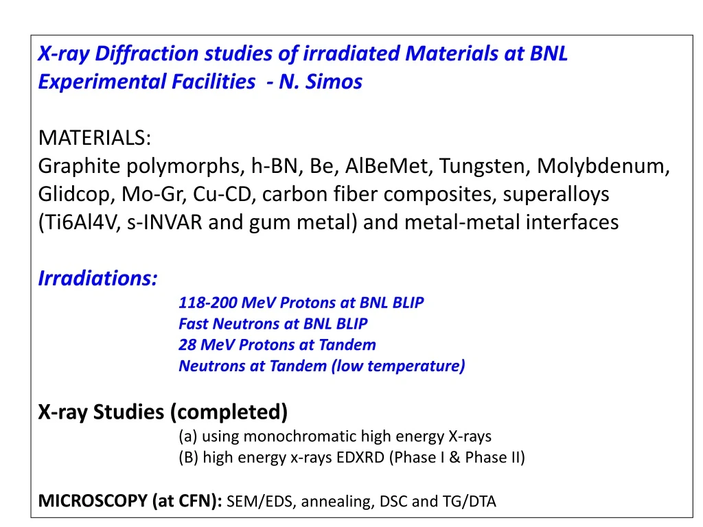
X-ray Diffraction studies of irradiated Materials at BNL Experimental Facilities - N. Simos MATERIALS: Graphite polymorphs, h-BN, Be, AlBeMet, Tungsten, Molybdenum, Glidcop, Mo-Gr, Cu-CD, carbon fiber composites, superalloys (Ti6Al4V, s-INVAR and gum metal) and metal-metal interfaces Irradiations: 118-200 MeV Protons at BNL BLIP Fast Neutrons at BNL BLIP 28 MeV Protons at Tandem Neutrons at Tandem (low temperature) X-ray Studies (completed) (a) using monochromatic high energy X-rays (B) high energy x-rays EDXRD (Phase I & Phase II) MICROSCOPY (at CFN): SEM/EDS, annealing, DSC and TG/DTA
28 MeV Proton Irradiation at Tandem Localized Damage Followed by EDXRD Studies
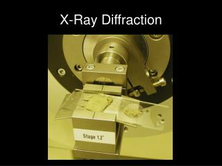
Multi-functional stage capable of handling Real size irradiated specimens, under vacuum and four point bending state of stress and eventually Heating/annealing via a portable, collimated laser beam Tensile stress-strain test From concept to a versatile experimental stage at X17B1 beamline at NSLS
stress strain
Load 1 Load 2 Good matching of experimental data
STRAIN MAPPING Energy Dispersive Diffraction Mode Like having imbedded inter-atomic strain gauges !!!! Ge-Detector “White Beam” y 1m diff. coll. incident collimation system k 3-12o~ 2 X-17B1 Transmission detector (radiography) 10-50 m Diffraction volume specimen
Graphite Important to know what occurs during irradiation and post-irradiation annealing (mobilization of interstitials/vacancies) This is what we observe in BULK What happens at the crystal level? How is E is affected or is strain in crystal related to bulk?
Interstitial defects will cause crystallite growth perpendicular to the layer planes (c-axis direction) Coalescence of vacancies will cause a shrinkage parallel to the layer planes (a-axis direction)
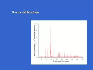
Graphite Various grades, including Carbon fiber composites under different irradiations This 002 peak also broadens asymmetrically, with a bias towards smaller angles indicating an increase in average interlayer distance. The (002) diffraction spot also broadens in single crystal images, suggesting a range of values for the interlayer distance
Goal is to correlate post-irradiation annealing observed macroscopically with shifts observed in XRD Global volumetric changes vs. crystal-level changes Activation Energy
Identification of lattice parameters RELATED to <c> and <a> (002) (004) (006) (008) (110) (100) (200) 2q
Interstitial defects will cause crystallite growth perpendicular to the layer planes (c-axis direction) Coalescence of vacancies will cause a shrinkage parallel to the layer planes (a-axis direction)