Download
1 / 68
680 likes | 794 Views
Implementation of Arbitrary Path Constraints using Dissipative Passive Haptic Displays. Davin K. Swanson PhD Defense George W. Woodruff School of Mechanical Engineering April 2, 2003. Committee: Wayne Book, ME, Chair Tom Kurfess, ME Kok-Meng Lee, ME Julie Jacko, ISyE

E N D
Implementation of Arbitrary Path Constraints using Dissipative Passive Haptic Displays Davin K. Swanson PhD Defense George W. Woodruff School of Mechanical Engineering April 2, 2003 Committee: Wayne Book, ME, Chair Tom Kurfess, ME Kok-Meng Lee, ME Julie Jacko, ISyE Chris Shaw, CoC
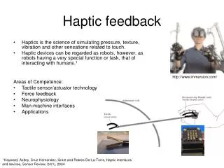
Haptic Displays • Definition: a physical man-machine interface which interacts with a user’s sense of touch • Types of haptic effects • Kinesthetic: movement of hands, limbs; point forces and torques • Tactile: fine touch; texture, temperature Swanson PhD Defense – April 2, 2003 Introduction
Energetically Active Haptic Displays • Most haptic displays are active • Electric motors • Pneumatics • Hydraulics • Voice coils • Advantages of active devices • May generate wide array of control efforts, haptic effects • Amplification of human effort • Rich control literature • Disadvantages of active devices • Machine failure or instability can lead to uncommanded motion • High forces may cause injury • Delicate environments may be damaged Swanson PhD Defense – April 2, 2003 Introduction
Energetically Passive Haptic Displays • Passive displays may only dissipate, redirect, store energy • Brakes, clutches, dampers (dissipative) • Continuously variable transmissions / CVTs (steerable) • All motive energy comes from user • Advantages of passive devices • Safety • Better acceptance by some operators (surgeons, astronauts) • Disadvantages of passive devices • Limited by passive constraint • May not generate arbitrary control efforts • Difficult to control; conventional controls not always suitable Swanson PhD Defense – April 2, 2003 Introduction
indirect coupling between user and environment Applications of Haptic Displays • Teleoperation – force-reflective masters • Virtual reality • Synergistic devices • Direct contact between payload/tool, user, interface • Example: cooperative manipulation Swanson PhD Defense – April 2, 2003 Introduction
Passive Haptics as Synergistic Devices • Passive devices are attractive for synergistic applications due to safety advantages • Tasks required of synergistic devices: Investigated previously by Swanson, Book Focus of this work Swanson PhD Defense – April 2, 2003 Introduction
Goals of this Research • Implementing path constraints is a weakness of dissipative devices (compared to steerable) • How well can dissipative devices perform this task? • How to fully evaluate performance? • Goals: • Develop control methodologies to implement path following on dissipative passive devices • Generate performance measurements to evaluate these controllers • Use human subject testing to evaluate these controllers • Correlate physical measurements with qualitative user opinion Swanson PhD Defense – April 2, 2003 Introduction
Overview of Presentation • Background • Controller Development • Experimental Testbed • Human Subject Testing – Design of Experiments • Human Subject Testing – Data Analysis • Conclusions Swanson PhD Defense – April 2, 2003 Overview
PTER “Scooter” Existing Passive Haptic Devices • PTER – Passive Trajectory Enhancing Robot • Charles, Book • 2 DOF • 2 dissipative, 2 coupling actuators • Used in this work • Cobots • Colgate, Peshkin, et.al. • Steerable devices • Use CVTs or steerable casters Swanson PhD Defense – April 2, 2003 Background
PADyC Existing Passive Haptic Devices • PADyC – Passive Arm with Dynamic Constraints • Troccaz, et.al. • Overrunning clutches limit velocities • Large workspace brake-actuated device • Matsuoka, Miller • 3 DOF (2 rotational, 1 prismatic) • particle brakes Swanson PhD Defense – April 2, 2003 Background
Existing Passive Haptic Devices • Florida 6 DOF hand manipulator • Will, Crane, Adsit • Particle brakes • PALM-V2 • Tajima, Fujie, Kanade • Variable dampers • That’s about it… Swanson PhD Defense – April 2, 2003 Background
Control of Dissipative Devices • PTER path following control (Davis, Gomes, Book) • Modified impedance controller • Velocity controller; computed desired forces • PTER obstacle avoidance (Swanson, Book) • Gomes velocity controller • Single degree-of-freedom (SDOF) control; selective actuator locking • PALM-V2 • Change damping to control velocity • Does not deal with sign differences between actual, desired velocity • Brake-actuated lower body orthosis (Goldfarb, Durfee) • Power comes from stimulated muscle contraction • PD / adaptive control of position and velocity • Applied force will always be in direction of desired velocity Swanson PhD Defense – April 2, 2003 Background
Control of Dissipative Devices • PADyC • Free motion, position constraint, region constraint • Trajectory constraint • Only velocity limits may be controlled • Define “box” of possible future endpoint positions • Velocity limits alter shape, size of box • Large-scale 3 DOF display (Matsuoka, Miller) • Viscous fields • Stiffness modeling • Virtual walls (similar to SDOF control) Swanson PhD Defense – April 2, 2003 Background
Control of Dissipative Devices • Very limited previous work in path-following control of dissipative interfaces • PALM-V2 does not address situations where force and velocity signs differ • Controlled brake orthosis always has force and desired velocity of same sign • PADyC has unique actuators (velocity magnitude constraints) • No directed work at providing path-following control for: • Arbitrary path shapes • Unknown external motive forces • Dissipative passive haptic displays • The door is wide open! Swanson PhD Defense – April 2, 2003 Background
Overview of Presentation • Background • Controller Development • Experimental Testbed • Human Subject Testing – Design of Experiments • Human Subject Testing – Data Analysis • Conclusions Swanson PhD Defense – April 2, 2003 Overview
Path Following Control • Goal: Allow user free motion along an arbitrary path while preventing motion orthogonal to that path • Conventional control methods • Assume active device • Typically calculate forces / torques to be applied • Example: impedance control Swanson PhD Defense – April 2, 2003 Controller Development
Velocity Field Control • Choice of high level controller • Control velocities rather than forces / torques • “Passive VFC” used by Li, Horowitz to control active manipulators • Define velocity field based on desired path • Low-level controller deals with achieving desired velocity • Velocity direction controlled, magnitude left to the user Swanson PhD Defense – April 2, 2003 Controller Development
Low Level Controllers • Form bulk of control work • Must drive link velocities towards desired velocity specified by velocity field • Three control concepts: • Velocity ratio control • Velocity ratio control with coupling elements • Optimal controller Swanson PhD Defense – April 2, 2003 Controller Development
Velocity Ratio Controller • Desired velocity may be transformed into link-space • Magnitude is unimportant… direction should be controlled • Control velocity ratios • Reduces controlled DOF by one • Makes sense! User has control of DOF along desired path Swanson PhD Defense – April 2, 2003 Controller Development
Velocity Ratio Controller • Compute ratio vector • Members represent amount each link must slow down • Lower number means more deceleration required • Negative number means direction change is necessary Swanson PhD Defense – April 2, 2003 Controller Development
Velocity Ratio Controller • Normalize the ratio vector by largest positive member • Goal of controller: guide system towards populated with all ones • Special case: no positive elements in • All axes must change direction • Solution: immobilize device • Use to generate control law Swanson PhD Defense – April 2, 2003 Controller Development
Velocity Ratio with Coupling Elements • Some interfaces may contain both dissipative and steerable elements • 2 DOF testbed used in this work • Two purely dissipative actuators • Two dissipative/coupling actuators • Allows for greater control flexibility • If coupling actuators are feasible, they are preferred • Strategy • Use a coupling actuator if feasible • Otherwise, fall back to standard velocity ratio controller Swanson PhD Defense – April 2, 2003 Controller Development
Velocity Ratio with Coupling Elements • Scale desired velocity for kinetic energy equivalence • Generate vector of signs of required accelerations • Compute matrix which represents effect of each actuator on each link velocity (-1, 0, or 1) • If any row of equals , the actuator represented by that row will be used • Otherwise, fall back on velocity ratio controller Swanson PhD Defense – April 2, 2003 Controller Development
Optimal Controller • In previous controller, dissipative and coupling elements separated • Use optimal control • Single control law dealing with both types of actuators • Often used to control “overactuated” systems • Minimize a cost function • Normally done offline to compute gains or control law • Dissipative haptic interfaces have serious nonlinearities • Signs of control efforts dependent on signs of link velocities • Perform minimization at every time step • States considered constant • Nonlinearities fall out Swanson PhD Defense – April 2, 2003 Controller Development
Optimal Controller • Optimization at each timestep • System is linear • If linear cost function is chosen, linear programming can be used • Fast, accurate, achievable • Goals of cost function • Drive system towards desired velocity • Primary goal of controller • Minimize energy loss • Secondary goal to favor coupling elements • Constraints • EOM of system • Actuator limits Swanson PhD Defense – April 2, 2003 Controller Development
Optimal Controller – CF Elements • Velocity control element • Controller must be free to deviate from desired velocity direction • Set of optimal inputs are control efforts and “optimal” desired velocities • Minimize angle between desired velocity and “optimal” desired velocity • To make it linear, maximize the numerator Swanson PhD Defense – April 2, 2003 Controller Development
Optimal Controller – CF Elements • Energy element • Minimize the reduction in kinetic energy • Use negative time derivative as member in the cost function • Simple, effective way to favor the coupling actuators • Use “optimal” desired velocity and actual velocity to estimate link accelerations • Final cost function Swanson PhD Defense – April 2, 2003 Controller Development
Overview of Presentation • Background • Controller Development • Experimental Testbed • Human Subject Testing – Design of Experiments • Human Subject Testing – Data Analysis • Conclusions Swanson PhD Defense – April 2, 2003 Overview
PTER – Experimental Testbed • PTER – Passive Trajectory Enhancing Robot Swanson PhD Defense – April 2, 2003 Experimental Testbed
PTER – Experimental Testbed • Five-bar linkage; two DOF • Actuators: electromagnetic friction brakes • Two dissipative (1, 2) • Two dissipative/coupling (3, 4) • PWM power supplies • 6-axis force/torque sensor on handle • Digital encoders (50,000 count/rev) Swanson PhD Defense – April 2, 2003 Experimental Testbed
PTER – Dynamics and Clutch Effects Swanson PhD Defense – April 2, 2003 Experimental Testbed
Unfiltered Velocity Estimate Filtered Velocity Estimate Position PTER – Control Software • Pentium II/450 with Servo-to-Go 8-axis interface card • QNX RTOS v6.1 • Serial port for force sensor • 500 Hz update rate • Link velocities computed from encoder measurements • Backwards difference + 25 Hz 4th order digital Butterworth filter Swanson PhD Defense – April 2, 2003 Experimental Testbed
0.85 Desired Path Starting Point 0.8 Applied Force 0.75 0.7 Y position (m) 0.65 0.6 0.55 0.5 -0.2 -0.1 0 0.1 0.2 0.3 0.4 0.5 0.6 X position (m) PTER – Controller Verification • Proof-of-concept tests of the three control concepts • Desired path: line at y=0.6 m • Starting point: (-0.1, 0.8) • Force applied by hand, roughly in (3, -1) direction • 5cm “buffer distance” Swanson PhD Defense – April 2, 2003 Experimental Testbed
PTER – Controller Verification • Two actuation smoothing routines; used to improve feel • Low velocity smoothing • Reduces chattering due to velocity sign changes • Velocity limit = 0.11 rad/s • Velocity direction error smoothing • Reduces chattering due to switching sides of the desired velocity vector • Angle limit = 0.10 rad Swanson PhD Defense – April 2, 2003 Experimental Testbed
PTER – Velocity Field Controller Swanson PhD Defense – April 2, 2003 Experimental Testbed
PTER – VF Controller w/Coupling Elements Swanson PhD Defense – April 2, 2003 Experimental Testbed
PTER – Optimal Controller Swanson PhD Defense – April 2, 2003 Experimental Testbed
Overview of Presentation • Background • Controller Development • Experimental Testbed • Human Subject Testing – Design of Experiments • Human Subject Testing – Data Analysis • Conclusions Swanson PhD Defense – April 2, 2003 Overview
Motivation for Human Subject Testing • Controller evaluation • Any haptic device has a human in the control loop • Human is very difficult to model • Comprehensive evaluation of controllers requires human subjects • Quantitative measurement of user opinion • User opinion important part of device operation • Typically requires multiple subjects, survey questions • Physical measurements are more accessible, predictable • Correlate survey responses with measured physical data Swanson PhD Defense – April 2, 2003 Human Subject Testing – Design of Experiments
Experimental Design • Task: point-to-point motion while following path • User instructed to move from start box to end box: • As quickly as possible • While following path Focus more on speed Swanson PhD Defense – April 2, 2003 Human Subject Testing – Design of Experiments
Template Design • Four templates representing different paths, areas of workspace Swanson PhD Defense – April 2, 2003 Human Subject Testing – Design of Experiments
Experimental Setup • Templates plotted full-scale • Locating board positioned on floor • Laser pointer provides visual feedback to user • Three locating pins to position templates • For each condition, user performs task six times • First 2 trials of each condition are practice • Data file recorded for each trial Swanson PhD Defense – April 2, 2003 Human Subject Testing – Design of Experiments
Experimental Conditions • Four templates • Nine control configurations • No control • Velocity ratio controller – low and high gains • Velocity ratio controller w/coupling elements – low and high gains • Optimal controller with no force input – low and high gains • Optimal controller with force input – low and high gains • Each subject uses all 36 combinations of conditions • Four templates presented in random order • For each template, nine control setups presented in random order Swanson PhD Defense – April 2, 2003 Human Subject Testing – Design of Experiments
Recorded Data • Physical data recorded for each trial • Positions • Endpoint forces • Actuator commands • Survey questions after each condition • NASA Task Load Index (TLX) • User ranks components of workload on 0-20 scale • Physical Demand (PD) • Mental Demand (MD) • Temporal Demand (TD) • Weighted combination of these used to calculate total workload • Weights based on subjects’ opinions of importance of each component • “Smoothness” component added (not used in workload computation) • Effort (E) • Performance (P) • Frustration (F) Swanson PhD Defense – April 2, 2003 Human Subject Testing – Design of Experiments
Overview of Presentation • Background • Controller Development • Experimental Testbed • Human Subject Testing – Design of Experiments • Human Subject Testing – Data Analysis • Conclusions Swanson PhD Defense – April 2, 2003 Overview
Collected Data • Nine total subjects • Three female, six male • Eight right-handed, one left-handed • Age: 19 – early 30s • 1292 total analyzed trials • Nine subjects • Four templates • Nine conditions • Four trials per condition • One set of four trials corrupted – not used Swanson PhD Defense – April 2, 2003 Human Subject Testing – Data Analysis
Physical Measurements • Path-average path error • Accuracy • Average desired-path velocity • Velocity estimated with six-step balanced difference + smoothing filter • Speed • Time-average endpoint force • Effort / fatigue • Endpoint acceleration FFT sum • Smoothness Swanson PhD Defense – April 2, 2003 Human Subject Testing – Data Analysis
Statistical Methods • Compute sample means of data by group • Compute confidence intervals based on standard error • 95% C.I. • Compare confidence intervals to determine whether population means of different groups are different Swanson PhD Defense – April 2, 2003 Human Subject Testing – Data Analysis
Controllers – Path Error • All controlled cases better than uncontrolled • VCLo better with a 90% C.I. • High gains better than low gains, except for optimal controllers • All optimal similar to VLo and VCLo Swanson PhD Defense – April 2, 2003 Human Subject Testing – Data Analysis
Controllers – Path Error Swanson PhD Defense – April 2, 2003 Human Subject Testing – Data Analysis