Download
1 / 29
290 likes | 435 Views
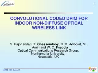
DH-PIM Employing LMSE Equalisation For Indoor Optical Wireless Communications. Z. Ghassemlooy, W. O. Popoola, and N. M. Aldibbiat Optical Communications Research Group, School of Engineering and Technology, The University of Northumbria, Newcastle, U.K.

E N D
DH-PIM Employing LMSE Equalisation For Indoor Optical Wireless Communications Z. Ghassemlooy, W. O. Popoola, and N. M. Aldibbiat Optical Communications Research Group, School of Engineering and Technology, The University of Northumbria, Newcastle, U.K. Web site: http://soe.unn.ac.uk/ocr ICEE 2006, Iran
Contents • Overview of Optical Wireless Communications (OWC) • Modulation Techniques • ISI and Equalisation • Simulation Results • Concluding Remarks ICEE 2006, Iran
Optical Wireless –What Does It Offer ? • High data rate (in particular line of sight) • Immunity to electromagnetic interference • Abundant unregulated bandwidth • High security compared with RF • Absence of multipath fading (due to the use of IM/DD) • Complementary to RF • Etc. ICEE 2006, Iran
OWC Links – Types • Line of sight • Uses single or multiple source and detector - Requires alignment between them • High bandwidth and no multipath induced ISI • Allows roaming • Suffers from blocking and shadowing • Diffuse • Uses single or multiple source and detector - No requirement for alignment between them • Robust to blocking and shadowing • Allows roaming • Multiple paths (reflections) • Result in inter-symbol interference (ISI). • Limited bandwidth - Due to large capacitance of the large area detectors ICEE 2006, Iran
Diffuse Systems – How to Combat Noise and Dispersion • Noise Filtering: Optical or electrical • Match Filtering: Maximises SNR, the optimum detection method in the presence of noise. (Time reversed copy of received pulse convolved with received data stream) • Coding: Block codes, convolution codes (MLSD), turbo codes. Increase performance by adding redundant data! • Equalisation: Channel distortion compensating filters: - Zero Forcing Equaliser (ZFE) - Minimum Mean Square Equaliser (MMSE) - Decision Feedback Equaliser (DFE) ICEE 2006, Iran
Pulse Modulation Analogue Digital Pulse Time Pulse Shape Pulse Time PSM PAM Anisochronous Isochronous Anisochronous Isochronous DPIM PIM DPPM PWM PIWM MPPM DPIWM PPM PFM DPWM difPPM SWFM PCM DH-PIM DifPAM RZ RB AMI Manchester NRZ NRZ(L) NRZ(I) Miller code Modulation Tree ICEE 2006, Iran
Symbol Symbol Symbol 1 2 3 (2) (10) (15) OOK M = 4 bits 0 0 0 0 1 1 0 1 1 1 1 1 T b Redundant Info. L = 24=16 slots space PPM L 1 Info. PIM A Info. DH-PIM a ( = 2) Time T 2 T s s H1 H2 Digital PTM Schemes ICEE 2006, Iran
Digital PTM Schemes OOK Simple to implement High average power requirement Suitable for Bit Rate greater tha 30Mb/s Performance detoreaites at higher bit rates PPM Complex to implement Lower average power requirement Higher transmission bandwidth Requires symbol and slot synchronisation DPIM Higher average power requirement compared with PPM Higher throughput Built in symbol synchronisation Performance midway between PPM and OOK DH-PIM The highest symbol throughput Lower transmission bandwidth than PPM and DPIM Built in symbol synchronisation Higher average power requirement compared with PPM and DPIM
DH-PIM- Frame Structure Nawras,2005
DH-PIM – Characteristics ICEE 2006, Iran
DH-PIM – Characteristics Synchronisation Higher packet transmission throughput ICEE 2006, Iran
Unit energy Equaliser Transmitter Multipath Optimum DH-PIM filter r ( t ) filter channel threshold (matched to encoder p(t) h(t) detector p ( t )) n-slot Compute P in s DH-PIM (n-1)th slot R n(t) sequence DH-PIM System ICEE 2006, Iran
Channel (ceiling bounce Model) y(t) ISI constituent -2T –T 0 T 2T 3T 4T 5T 6T 7T 8T t RMS delay spread OWC - Channel Developed by Carruthers and Kahn - Channel impulse response is fixed for a given position of Tx, Rx and intervening reflectors H(0) = path loss a = 2H/c, H = height of ceiling above Tx and Rx, c is the speed of light u(t) = unit step function ICEE 2006, Iran
OWC –Equalisation • Non-Linear • DFE • ML Symbol detector • MLS • Linear • Lattice • Transversal • Zero Forcing • LMS • Fast RLS • Square-root RLS Linear Equaliser:Traversal filter structure that has a computational complexity which is a linear function of the channel dispersion length. ICEE 2006, Iran
Noise ISI OWC - Equalisation – contd. Noise nk yk Ik Multipath channel Equaliser Cj Rx Filter Tx Filter • Discrete equivalent of the convolution of the Tx filter, channel and Rx filter with the information sequence Ik • Equaliser output (estimate) Where {cj} are the 2K +1 complex-valued tap weight/coefficients of the filter. ICEE 2006, Iran
Signal ISI Noise Equaliser with infinite number of taps, tap weights could be selected such that the ISI component is reduced to zero. For practical case: j = k Linear Zero ForcingEqualiser • With a frequency response = h(t)-1. • Able to reduce ISI term at sampling points {qn} is simply the convolution of {cn} and {fn}. Simple to implement, but not effective with noise. Compensate for the channel distortion at the expense of noise due a large gain in the frequency range where attenuation is high ICEE 2006, Iran
Least Mean Square Error Equaliser • Relaxing the zero ISI by selecting Cj such that the combined power of the residual ISI and additive noise at the equaliser output is minimised . I.e. minimising the mean error square: The MSE for the equaliser 2K+1 taps is The LMSE solution is obtained by dJ(k)/d{cj}. Autocorrelation matrix cross-correlation vector yT is the transpose of matrix yk-j and I represents the training signal. ICEE 2006, Iran
Autocorrelation matrix cross-correlation vector LMSEE –contd. Where • In contrast to zero-forcing equaliser, the LMSEs solution depend on the statistical properties of the noise as well as the channel induced ISI yT is the transpose of matrix yk-j and I represents the training signal. ICEE 2006, Iran
Gen L-DH-PIM Gen. Rand. {OOK} Start Enter No_symb Enter Rb and Drms 1<Drms<15ns Enter ; SNR -70<<-30 dBm Evaluate Cm, hk; No Out=Cm*hk*I + No No Outk = Ik? Yes Error = Error + 1 Error = Error Last slot ? SER = Error No of slots No Yes Last ? Last Drms ? Yes No No Yes Stop Simulation Process ICEE 2006, Iran
Simulation Parameters ICEE 2006, Iran
Results –Eye Diagrams 8-DH-PIM2 at Rb = 100 Mbps, Drms = 15 ns and = -30 dBm. Unequalised Equalised ICEE 2006, Iran
10-4 Results –Slot Error Rate vs SNR Significant improvement -37.5 and -35.5 dBm of average optical power @ SER of 10-4 ICEE 2006, Iran
8-DH-PIM R =100Mbps; 3-Tap LMSE 2 b -1 10 -2 Probability of slot error (SER) 10 D =2ns r m s -3 D =4ns 10 Unequalised r m s D =6ns r m s D =10ns r m s D =2ns r m s D =4ns r m s Equalised D =6ns r m s -4 D =10ns 10 r m s -46 -44 -42 -40 -38 -36 -34 Average optical power requirement (dBm) Results – Slot Error Rate vs Avg. Optical Power ICEE 2006, Iran
Results –Slot Error Rate vs SNR ICEE 2006, Iran
Results –Power Penalty vs DT DT = DrmsRb ICEE 2006, Iran
Results –Power Penalty vs DT similar performance in very dispersive environment 3-taps DT = DrmsRb LMSE is better in less dispersive channels (DT < 0.2). LMSE compensates for both dispersion and noise (dominant) ICEE 2006, Iran
Concluding Comments Employing equalisation in DH-PIM leads to: Reduced optical power level requirement at high data rate and highly dispersive channels Improve error performance in a dispersive channel LMSE offered similar performance to LZEF, at highly dispersive channel, but better performance in less dispersive channels (line of sight) DH-PIM with equalisation is an attractive modulation scheme for OWC where there is a need for high throughput
Thank you! ICEE 2006, Iran
OWC – Issues + Solutions • Shadowing in non-line of sight links - Diversity schemes • Limited power (safety reason) - Power efficient modulation techniques • Noise due to the ambient light sources • Optical/electrical filtering • Modulation scheme with no or very little frequency components at the low frequency bands • Dispersion (due to multipath) • Equalisation • SNR variation with the distance and ambient noise ICEE 2006, Iran