Download
1 / 60
600 likes | 615 Views
Advanced Studies Institutes Physics at LHC Prague 6-12 July 2003. The TOTEM Experiment. Karsten Eggert CERN, EP Division on behalf of the TOTEM Collaboration http://totem.web.cern.ch/Totem /. Collaboration. The measurement of s tot. Historical : CERN Tradition (PS-ISR-SPS)

E N D
Advanced Studies Institutes Physics at LHC Prague 6-12 July 2003 The TOTEM Experiment Karsten Eggert CERN, EP Division on behalf of the TOTEM Collaboration http://totem.web.cern.ch/Totem/
The measurement of stot • Historical : CERN Tradition (PS-ISR-SPS) • Dispersion relation fit (logs)g, g=2.20.3 (better fit today 2.0) • Current models predictions: 100-130mb • Aim of TOTEM: ~1% accuracy • Absolute calibration of Luminosity
~150m ~215m Optical Theorem
Track chambers CSC Cathode strip read-out for vertex reconstruction 5 planes on each telescope Space resolution better than 0.5mm Trigger by RPC Two double gap chambers Pad read-out with projective geometry Time resolution ~1ns T1 Inelastic telescope T1 telescope η~3.1 to 4.7 on each side
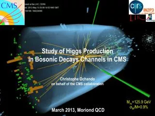
RAILS ARE ASSEMBLED ON A TRUSS STRUCTURE, TO WITHSTAND THE FLEXURAL LOAD THE TRUSS IS COMPLETELY RESTRAINED ON THE OUTERMOST SPACER RING PUSH/PULL RODS AT THE END TIE THE 2 TRUSSES AND LIMITS THE TORSION BASIC SOLUTION: STEEL MADE, ONE TRUSS WEIGHS ROUGHLY 120 Kg PUSH ROD: COULD BE MADE OF ALUMINIUM OR FIBERGLASS (BETTER PARTICLE TRANSPARENCY) AND/OR ARC-SHAPED PUSH/PULL RODS TRUSS
T1 telescope simulation • T1 description in ORCA • (CMS OO simulation) • Distribution of fitted tracks extrapolated to the collision plane. • The circle indicates the actual beam pipe diameter
T2 Silicon detector in front of CASTOR 5.3 < h < 6.7 on each side 13570 400 T1 and T2 and the forward Roman pots allow fully inclusive trigger (including diffraction). The trigger will be a two side coincidence : (T1 or T2) left X (T1 or T2) right (T1 or T2) left X (proton in RP) right (proton in RP) left X (proton in RP) right Lost events: < 1% acceptance for diffractive protons: >90 % independent of x=Dp/p
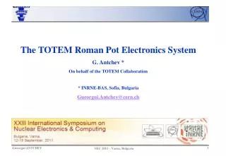
Lightweight Structure Space for services 470 mm Bellow Weight estimation: ~30 Kg Thermal Insulation 400 mm
Charged particle fluxes Hits per plane hits Charged Particle Fluxes for a luminosity of 1028 at T1 1.5 Hz/cm2 at T2 40. Hz/cm2 (1. plane) with beam pipe Totem only ( old ) Radiation hardness T1 can operate for a few years at L=1032 T2 can operate for a few years at L=1033 with beam pipe
Elastic scattering Impact picture and Regge models TOTEM goals: measure t-distribution to lowest possible t (t~10 –3 GeV2 ) extrapolation to t=0 with a precision of <0.5% measure over largest possible t-range (t ~10 GeV2)
TOTEM Optics Conditions LTOTEM~ 10-6 x 1034 cm-2 s –1 ~ 1028 cm-2 s –1 TOTEM needs special/independent short runs at high-b* (1500m) Scattering angles of a few mrad High-b optics for precise measurement of the scattering angle q* = e / b* Reduced number ofbunches to avoid interactions further downstream s* = e b* Parallel-to-point focusing: Trajectories of proton scattered at the same angle but at different vertex locations
Ly(1540) vx(1100) Ly(1100) Lx(1100) vx(1540) Lx(1540) vy(1540) vy(1100) High b optics: lattice functions v= (b/b*)1/2 cos m(s) L = (bb*)1/2 sin m(s)
Elastic Scattering acceptance b* = 1540 m b* = 1100 m
t acceptance for the two proposed optics acceptance dependence on detector position t=0.004 GeV2 A=44% t=0.01 GeV2 A=67% b=1100m t=0.004 GeV2 A=64% t=0.01 GeV2 A=78% b=1550m
and t – resolution versus the azimuthal angle f assumed detector resolution 20 mm df (rad) s(t)/t
total beam angular divergence =0 t-resolution (one and two arms) versus detector resolution s(t)/t (1 arm) v dependence! s(t)/t (2 arms) coplanarity
Errors on the extrapolation to t=0 • Beam angular divergence sq=(e / b*)1/2 • Optical functions • Beam position • Crossing angle • Detector resolution: statistics and systematics (detector offset) • RP station alignment • Background (beam halo, double pomeron exchange…)
Elastic Cross section (t=0): stat. and syst. errors L=1028 cm-2 s-1 run time = 4 . 104 sec 10mm detector position uncertainty
Ldt = 1033 1037 cm-2 2.104/GeV2 15/GeV2 -t(GeV2) Large t scattering 1 eff.day (105sec) at high b and 18 m b*=18m b*=1540m ds/dt (pp) (mb/GeV2) (M. Islam)
High and stable efficiency near the edge facing the beam, edge sharpness < 10 mm Try to do better than present technology guard rings ~0.5 mm Detector size is ~3x 4 cm2 Spatial resolution ~20 micron Systematics ~ 20 micron Moderate radiation tolerance (~1014 n /cm2 equiv) CMS Hybrid ~3cm Detector requirements
RD39/NA60 have investigated/used silicon at cryogenic temperatures (~ 100-130 K) Studies hint at possibility of operating silicon microstrip without guard rings at LN temp. K.Borer et al., “Charge collection efficiency of irradiated silicon detector operated at cryogenic temperatures” NIM A 440 (2000) 5. L.Casagrande et al.,"A new ultra radiation hard cryogenic silicon tracker for heavy ions beams“ NIM A (2002) 325-329. S.Grohman et al., “Detector development for TOTEM Roman Pots”, IX Blois Workshop on El. and Diff. Scatt., Pruhonice, Czech Republic, (2001), 363. In 2002 we have performed a first measurement on cold edgeless silicon detector Cold Silicon Z. Li et al, "Electrical and TCT characterization of edgeless Si detector diced with different methods", IEEE NSS Proc., San Diego, Nov. 2001
Reconstruction of the cut edge Hits in the cut detector Hits in the telescope (all good tracks) Efficiency Edge at: 0+20micron
p+ C p+ D B A B A n+ n+ Development with planar technology cut edge n+ ring (20 mm) at30mmfrom p+ set at the same pot as backplane hope: n+ ring stops the C current B under control with temperature test of various configuration this summer goal: increase working temperature
PLANAR-3D DETECTORS TRADITIONAL PLANAR DETECTOR + DEEP ETCHED EDGE FILLED WITH POLYSILICON p + Al E-field n + Al i n + Al signal a.u. position [mm] Edge sensitivity ~20 mm Leakage current =6nA at 200V Brunel, Hawaii, Stanford
3D DETECTORS AND ACTIVE EDGES Brunel, Hawaii, Stanford • 15 mm InfraRed beam spot • FWHM = 772 mm • Edge Al strip width = 16 mm • INSENSITIVE EDGE • (INCLUDING 16 mm • Al STRIP): • (813 - 772) / 2 = 21 mm • EDGE SENSITIVITY <10 mm • COLLECTION PATHS ~50 mm • SPATIAL RESOLUTION 10-15 mm • DEPLETION VOLTAGES < 10 V • DEPLETION VOLTAGES ~105 V at 1015n/cm2 • SPEED AT RT 3.5 ns • AREA COVERAGE 3X3 cm2 • SIGNAL AMPLITUDE 24 000 e before Irradiation • SIGNAL AMPLITUDE 15 000 e- at 1015n/cm2 • CERN Courier, Vol 43, Number 1, Jan 2003
3D response to particles Brunel, CERN, Hawaii, Stanford Pulse height • Small bias 5-8 V • Speed 1.5, 3.5 ns • Radiation hardness MIP MIP Ileak = 0.45 nA (average) 200 mm Ileak = 0.26 nA (average) 100 mm C = 0.2 pF per electrode 1x10¹⁵ p/cm2 20oC
Design of the Roman Pot is focused on three main phases: • Design of the Pot • Design of the Roman Pot Station • Integration in the Tunnel • Main items: • Secondary Vacuum : outgassing and RF shielding • Mechanical Design of a thin window • Integration of detectors inside the pot: mounting, cooling • Design of a flange to routing the detector’s services outside the pot • High mechanical precision ( < 20 mm) and reproducibility
Density (Kg/m3) Young Modulus (GPa) Yield Strength (Mpa) Radiation length Xo (mm) Aluminum 6063 2800 72 250 89 Stainless Steel 316L 8000 200 280 17.6 Copper 8900 110 152 14.3 Beryllium IF-1 1900 303 300 350 Titanium 6AL4V 4700 110 1100 35.6 Inconel 718 7800 200 1050 17.6 deformation (m) 0.1 mm Inconel 718 1 atm. stress Pa
Brazing Pot window Thin window Technology issues • Brazing: • Inconel looses ~30% of the strength • Low limit on the thickness of the joints • Brazing inside the pot -> dead space • Electro erosion: • Low Yield of material • Increase of Porosity • Bottom of the pot flat -> no dead space Both technologies are available at CERN and must be tested on prototypes
Prototyping and Test of the Pots at CERN (July 2003) • Brazing test on Folded Inconel Foils • Production of 5 window prototypes to be tested under pressure TEST procedures • Cycling load 0bar/1bar -> no permanent deformations • Thermal test cycling from RT to 300oK with and without pressure load -> no permanent deformations • Increasing of the pressure till rupture to define the ultimate load • 1 Pot Prototype for RF Pick up test on electronics • Production of 1 mock-up of the pot with dummy detectors to have a full integration exercise with the services
Conceptual Design of the Roman Pot detector CMS Tracker Hybrid 3cm Thermal analysis
Cryogenic Cooling (F.Haug, AT/ECR) • Two main options: local cooling or passive elements • Active local cooling system • Passive system : Heatpipes, Peltier Cells (preferable solution) • Cold source at 80oK -> pulse-tube (no vibrations) • Other systems as Joule-Thompson nitrogen flow are under investigation • QRL transfer line of LHC machine = NO ! Heat loads ~12 watt/pot > 230oK 2 Watt few mWatt DT ~ 5oK Heatpipe ~ 1500mm DT ~ 20oK 130oK 80oK Pulse tube
TOTEM Test Beam Read/Out Hybrid ~RT Liquid Nitrogen Reservoir (77oK) Kapton Pitch Adapter (Thermal bridge) Edgeless Detector (130oK) Vacuum Vessel
Pot with Secondary Vacuum Reference Pin Pot Carbon Fiber Frame APV25 Cooling contact Pitch Adapter x-y Module Silicon Sensor 40mm x 40 mm Precision Reference Pin Forward Proton Thin window 0.1mm : Secondary vacuum + RF shielding
PCB cards Cooling Connectors Flat cables D-Connector Flange with double sided D-Connectors Flange with feeding through PCB cards
What has been done for the Roman pot system: • Two solutions have been designed: Symmetric distribution of the loads but less favorable access for maintenance Not symmetric loads but optimized access For Both solutions • A compensation system based on external vacuum pumps allows for a fine regulation, releasing the force on the pots • A capacitive system accounting the relative position of the top-bottom pots, • Integration of two Roman Pot stations between the TAN and D2
Compensation bellow Pot Lever Arm Capacitive sensor Roman Pot Device (Second Version)
Horizontal Roman Pot Station Measuring and cross-calibration purpose LHC Beams
Collimator QRL BPM TAN Racks Roman Pot Station (made of two RP devices)
Impedance Issues • LHC Impedance requirements impose small resistivity and small volumes: • when the Roman pots are close to the beam in data taking mode the estimated impedance is 0.1 mW and it is by far lower than the impedance budget allowed for the machine 250 mW , assuming a pot in Steel. • Operation restriction for near-beam detectors: • Image Current -> heat deposited on the pot by ohmic heating • RF Fields -> noise induced on the detectors and the electronics • Both are related to LHC bunch structure: • for TOTEM special runs -> 36 bunches 2 ms spaced
A novel detector for measuring the leading protons - the Microstation - is designed to comply with the LHC requirements. • a compact and light detector system • integrated with the beam vacuum chamber • geometry and materials compatible with the machine • requirements • mm accuracy in sensor movements • robust and reliable to operate • Si strip or pixel detector technology Development in cooperation with the LHC machine groups M.Ryynänen, R.Orava. /Helsinki group
Microstation Inch worm motor Emergency actuator 6cm Inner tube for rf fitting Space for cables and cooling link Detector Space for encoder Note: A secondary vacuum is an option. M.Ryynänen, R.Orava. /Helsinki group
Radiation background on the Roman Pot (D.Macina, N.Mokhov) Assumptions: • Simulation has been done from IP5 to Q7 (v. 6.4, = 0.5 m) • Peak luminosity is L=1034 cm-2 s-1 • Absorbed dose is normalized to : 180 days, 24 hours per day, <L> = 0.5 · 1034 cm-2 s-1,equivalent to 6.22·1015 non-elastic events per year Results: Accumulated radiation dose around the RP is ~ 103 Gy/yr Annual Fluence of Hadrons on the tunnel ground~109cm-2 Radiation hard components (cooling, local triggers, power supplies…..) are required
Radiation fluence in the RP silicon detectors(N.Mokhov,I. Rakhno,Fermilab-Conf-03/086) Maximum fluence (1014 cm-2) for charged hadrons (E>100 KeV , L= 1033 cm-2 s-1, t=107s): RP4 (215 m) Vertical: 0.58, Horizontal: 6.7 Dose (104 Gy/yr) RP4 (215 m) Vertical: 0.37 (max: 1.9), Horizontal:1.2 (max:55) Main source of background: pp collisions Tails from collimators and beam-gas scattering ~ 0.1-1% Radiation level manageable
Interactions with the machine Design and construction of the Roman pots together with EST Tests and production of the prototypes Risk analysis of the secondary vacuum and of the operation LHC impedance requirements Radio frequency shielding Integration and services into the tunnel Choice of the cryogenic cooling system for the Silicon detectors LHC vacuum requirements: NEG coating and bake-out at 300 K