Download
1 / 17
170 likes | 182 Views
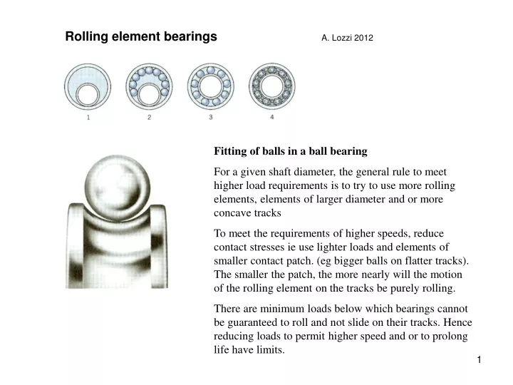
Rolling element bearings A. Lozzi 2012. Fitting of balls in a ball bearing For a given shaft diameter, the general rule to meet higher load requirements is to try to use more rolling elements, elements of larger diameter and or more concave tracks

E N D
Rolling element bearings A. Lozzi 2012 Fitting of balls in a ball bearing For a given shaft diameter, the general rule to meet higher load requirements is to try to use more rolling elements, elements of larger diameter and or more concave tracks To meet the requirements of higher speeds, reduce contact stresses ie use lighter loads and elements of smaller contact patch. (eg bigger balls on flatter tracks). The smaller the patch, the more nearly will the motion of the rolling element on the tracks be purely rolling. There are minimum loads below which bearings cannot be guaranteed to roll and not slide on their tracks. Hence reducing loads to permit higher speed and or to prolong life have limits.
Choice of bearings for a given shaft or bore diameter For a given standard shaft diameter there is a range standard housing bore diameters that can be accommodated with bearings of higher wall heights. Likewise for given bore diameters there are a range of shaft diameters that can be accommodation. Further for given shaft and bore diameters there are a range of bearing widths that can be used. This range of heights and widths of bearings are referred to as bearing ‘series’.
Choice of load ratings Looking at bearings for a shaft diameter of 50mm, we see that outer diameters from 65 to 130 mm can be accommodated. For increasing outer diameters the dynamic load rating increases. Note that the width of these bearings also increases from 7 to 31 mm. These are standard series bearings. This table also shows that for a given bearing ID and OD there are choices of bearing widths. For example 50 ID, 80 OD there are two widths possible: 10 & 16 mm. There are ranges of bearings not shown in standard catalogues that are referred to as narrow and very narrow series, for which one typically pays considerably more.
Choice of bearing type Note that in the space taken up by a 50 ID, 110 OD &27 mm wide deep groove ball bearing, shown on the previous slide, we could substitute a twin row self aligning ball bearing, or a twin row spherical rollers (also self aligning) ball bearing. These 3 bearings would have quite different axial and radial load bearing characteristic and angular aligning requirements. The cost will also differ significantly between them. The bore of these bearings may be cylindrical or tapered (conical).
Plummer blocks These standard bearing housing have been developed so that bearings can be contained rigidly in a clean, lubricated envelope, and be mounted to welded frames with minimal preparation. A typical housing is shown in side section view at left and in front view above. By choosing spacers to fit on either or both sides of the bearing, the clearances at the sides of the bearings can be removed and the housing can be made to take axial loads.
Tapered bore bearings locked on parallel shafts Spilt tapered sleeves may be used together with bearings with tapered inner bore, to clamp a bearing anywhere along a parallel sided shaft. Note that the tapered sleeves are split down their length. The nut is used to close the space between the inner bore of the bearing and the shaft. The clamping force must not be so large as to cause interference between the rolling elements and the tracks. Hydraulic pressure is used on larger bearings to release the grip between the sleeve and the bearing.
Rolling element designs, to suit different proportions of radial and axial loads. The hollow elements are developed to take some significant shock loads. Ref - P. Orlov A range of bearings with a wide capacity for radial and axial loads, and some combination
Selection of a bearing according to its dynamic load and its expected life: This the number of millions of revolutions that is required from the bearing This is the Equivalent Dynamic Load that the bearing carries which is calculated using the radial and axial components of the actual load. The Equivalent load is calculated from the combination of radial and axial loads that the particular application requires. The linear coefficients X & Y vary with the bearing type and also may with the proportion of the radial to axial loads. The life of a bearing in a particular application may then be calculated from this exponential function. The ratio is of the Basic Load rating ( C - provided by the manufacturer for each bearing) and the Equivalent load that the bearing will be subjected to. p = 3 for ball, 3.333 for roller bearings For each bearing there a minimum load that is required to ensure that the rolling elements roll and do not slide. Hence one cannot be assured of very long life by just reducing the load or selecting a bigger bearing. Similar calculations can be done for static loads. Corrections can be made for fluctuating loads.
In most assemblies it is most important not to ‘over-constrain’ a shaft (ie not to have more than one bearing doing the same task: The bearing at left restricts axial and radial movement of this motor’s rotor, the bearing at right (the output end of the motor) takes radial loads only and permits axial movement. Some axial movement is necessary for differential thermal expansion of the assembly and variations in manufacturing tolerances. Typically it would be wrong for axial thrust to be taken at both ends of the shaft, because almost certainly the result would be that the bearings would fight or load each other.
A gear wheel that takes both axial and radial loads, is held in place by self aligning bearings. Note that these bearings allow considerable angular misalignments between the centre lines of the two bearings, within the housing or frame, on which the gear wheel is mounted. Note also that the RH bearing locates the shaft axially.
B A A B F F With almost no exceptions bearings are designed to take axial and radial loads only. There is almost no bearing that is designed to take a moment about an axis perpendicular to the centre line of its shaft. The wheels above may transmit a moment to the shaft (by force F) but only by transmitting two transverse forces (A & B), separated by some distance, to the shaft.
To ensure that even in rigid installations as exemplified by the above drawing, the alignment of bearings should not ‘fight’ with each other. For example the double row spherical roller bearing should not interfere with the alignment of the spherical thrust roller bearing at the bottom of the shaft. This can be achieved if the two bearing’s outer track spherical radii share a common centre.
Special bearings for limited bending moment. There is also an exception to bearings not being made to accept moments. There is a range of very deep grove ball bearings which can cope with a relatively small moment. These are especially made for pulley sheaves. Note that for the larger sheave the moment is taken by two parallel bearings.
A ‘Cooper’ bearing, in which the tracks are splits horizontally, along the CL of the shaft. This allows the bearing to be serviced or replaced without removing the shaft
Three and four point contact bearings Their inner and or outer track split perpendicularly to their CL. By this means bearing of limited OD, can be fitted with more balls and with larger contact areas. When preloaded these bearings can carry large axial loads from both directions, together with large radial loads. On the negative side, the large contact areas can generate a relatively large amount of waste heat, hence lubrication is critical. Examples of uses: jet engines, turntables in machine tools, where large axial, transverse loads as well as a bending moment may be present, critical and expensive applications.
Bearings for very large bending moments. Above are a range of multiple contact bearings, developed predominantly to be used as the base bearings for cranes. The larger the crane the more elaborate and sophisticated are the slewing bearings made for them. There is no mention of bearings for tank turrets, one may presume that they are even more interesting.
Plain slide Bearings For slow moving contact velocities bearing manufacturers typically make a range of plain slide bushings that range from using steel on steel, for very high contact loads, to steel on bronze, then steel on plastic for lesser loads. Spherical cup bearings are shown at left but cylindrical and other designs are available. Bushings are selected on the basis of a simple formula: K are constants depending on the material type, P is the pressure, V is the sliding velocity which may be raised to some power such as 1.5. There is usually upper limits to the pressure and velocity.