Download
1 / 11
180 likes | 866 Views
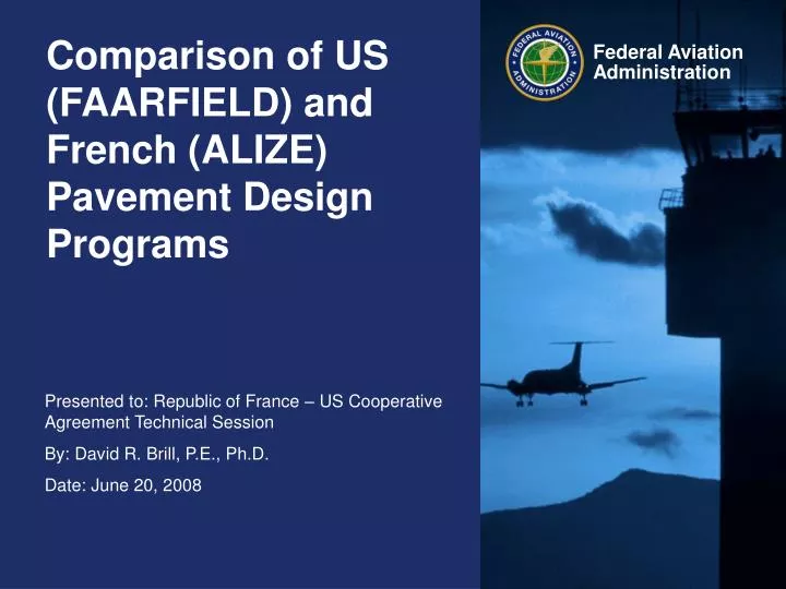
Comparison of US (FAARFIELD) and French (ALIZE) Pavement Design Programs. FAA (AC 150/5320-6E) New Flexible Conventional Stabilized base New Rigid Overlay on Flexible: HMA on flexible PCC on flexible Overlay on Rigid: HMA on rigid PCC on rigid. LCPC (Guide technique) Flexible

E N D
Comparison of US (FAARFIELD) and French (ALIZE) Pavement Design Programs
FAA (AC 150/5320-6E) New Flexible Conventional Stabilized base New Rigid Overlay on Flexible: HMA on flexible PCC on flexible Overlay on Rigid: HMA on rigid PCC on rigid LCPC (Guide technique) Flexible Thick bituminous Pavements with base layers treated with hydraulic binders Composite structure Inverted structure Cement concrete Pavement Types
FAA (AC 150/5320-6E) Thickness design is deterministic based on established failure models. Procedures are sufficient to provide a 20-year design life. (DOT/FAA/AR-04/46). However, variations in as-built pavement thickness, material strength, etc., are considered in construction specifications (percent-within-limits pay factors). LCPC (Guide technique) Thickness design directly incorporates probability concepts. Assign risk (defined as the probability of failure occurring before a given number of years). Calculated risk based on: Variation in lab fatigue tests. Variation in as-built layer thickness. Probability Considerations
FAA (FAARFIELD) Layered Elastic (LEAF) for flexible and preliminary rigid iterations. Strains computed at predefined evaluation points. Multiple-gear: strains computed for all wheels. 3D finite element (NIKE3D) for final new rigid and rigid overlays. Single-slab edge stress model. Free edge stress reduced by 25% to account for load transfer at joints. LCPC (ALIZE) Layered Elastic (Burmister) model to compute stresses and strains. 3D Finite Element planned for rigid but not implemented. Currently, slab discontinuities accounted for through kd factor in failure model. Strains computed for complete landing gear (including nose gear). Structural Models
FAA (FAARFIELD) Subgrade characterized by CBR (flexible) or k-value (rigid). (Design CBR = mean minus 1 standard deviation.) Recommended to input CBR or k and allow program to convert to E modulus for design. However, E can be entered directly. LCPC (ALIZE) Subgrades are classified PF0 – PF4 E modulus is assigned to each soil bearing class. Soil bearing class may be determined by plate load or CBR test, or deflection under a 130-kN standard axle. Material Properties (Subgrade)
FAA (FAARFIELD) Most material properties are fixed or constrained within limits set to represent standard FAA materials in AC 150/5370-6B. HMA (Item P-401) Modulus fixed at 200,000 psi (surface) or 400,000 psi (base). Temperature not a standard design variable. PCC (Item P-501) Modulus fixed at 4,000,000 psi Flexural strength R for design is related to specification requirement for 28-day strength (flexural beam test). Aggregate layers (P-154, P-208, P-209) Modulus varies depending on underlying layer. Program subdivides into sublayers (max. 10 in. thick.) LCPC (ALIZE) Material library exists for standard materials. Material characterization for design includes: Temperature-vs-modulus data (HMA). Frequency effects (HMA) Fatigue test data (all materials). PCC Strength classes 1 – 6 Modulus based on class. Concrete strength by indirect tension test. Used for steel design – concrete thickness based on fatigue tests. Aggregate layers Modulus varies depending on underlying layer. Program subdivides into sublayers (max. 25 cm thick.) Material Properties
FAA (FAARFIELD) All design based on assumed taxiway wander, = 30.5 in. (0.775 m). Miner’s law for mixed traffic (Cumulative Damage Factor). Pass-to-coverage ratio computed based on depth to layer of interest: Rigid – at surface. Flexible (subgrade) – at top of subgrade Flexible (HMA) – at bottom of HMA surface. For tandem wheels, adjust P/C ratio by a factor between 1 and number of wheels in tandem (flexible). Airplane speed is not a design variable. LCPC (ALIZE) Damage may be computed with or without wander. Input wander () for each airplane in traffic mix. Miner’s law for mixed traffic. For tandem wheels, damage computed for multiple peaks following a fatigue law: Frrequency for HMA fatigue model is a function of airplane speed. Traffic Models
FAA (FAARFIELD) For flexible pavements, coverages to failure for vertical strain computed at the top of the subgrade: Not considered for rigid pavements. LCPC (ALIZE) Check that vertical strain at the top of the subgrade is less than a limiting value: NE = number of equivalent axles. A is a factor determined by the traffic (CAM, or coefficient of aggressiveness). How to obtain NE and A for airport pavements? Checked for all pavement structures. Failure Models (Subgrade)
FAA (FAARFIELD) HMA horizontal strain checked at the bottom of HMA surface layer. Heukelom & Klomp model: C = coverages to failure EHMA = HMA modulus, assumed 200,000 psi. New model in development based on energy principles (RDEC). LCPC (ALIZE) HMA strain checked at bottom of HMA layers: 6 = failure strain in HMA fatigue test at given temperature & frequency N = airplane passes CAM = equivalence to reference highway axles (How obtained?) b = fatigue curve slope k = temperature factor kr= risk factor ks = low bearing capacity compensation factor kc = global adjustment (“calibration”) factor (~1.0 – 1.3) Failure Models (HMA)
FAA (FAARFIELD) Failure defined by SCI=80. Relate coverages to computed edge stress by: C = coverages to failure SCI = structural condition index DF = design factor = R/ F's = stabilized base compensation factor Fc = calibration factor = 1.12 a, b, c, d = fitting parameters LCPC (ALIZE) Check allowable tensile stress in both concrete and cement-treated base: 6 = failure stress in bending fatigue test N = airplane passes CAM = equivalence to reference highway axles (How obtained?) b = fatigue curve slope kr= risk factor ks = low bearing cap. compensation factor kc = global adjustment (“calibration”) factor (~ 1.40 – 1.50) kd = discontinuity & temperature factor Failure Models (Rigid)
Subjects for Discussion • How to obtain equivalence to reference highway axles (CAM) for airplane traffic? • How is pass-to-coverage (or equivalent) determined in ALIZE for a given wander ? • Material library for French standard materials. • Global adjustment factor – sources for model calibration. • Frost protection provisions.