Download
1 / 1
10 likes | 123 Views
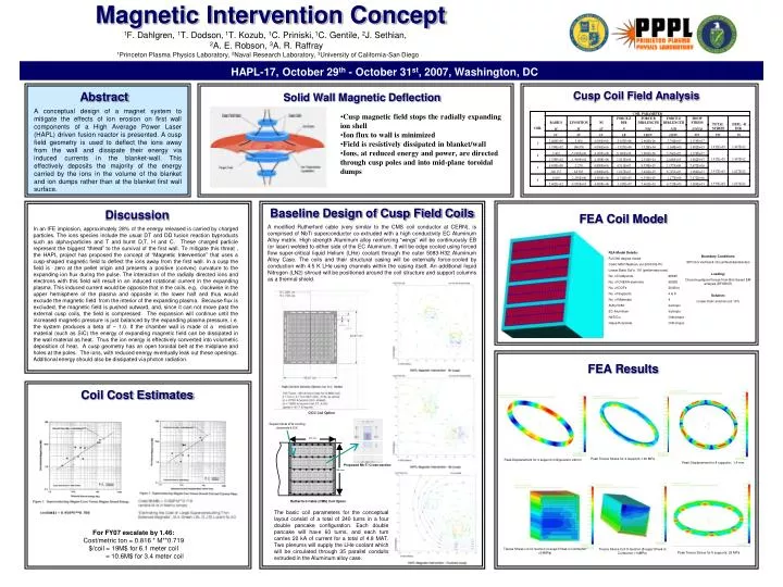
Magnetic Intervention Concept. Cusp Coil Field Analysis. Peak Displacement for 4 support configuration: 24mm. Peak Tresca Stress for 4 supports: 140 MPa. Peak Displacement for 8 supports: 1.4 mm. Tresca Stress Coil X-Section (4-supp’t.Peak in Conductor =34MPa).

E N D
Magnetic Intervention Concept Cusp Coil Field Analysis Peak Displacement for 4 support configuration: 24mm Peak Tresca Stress for 4 supports: 140 MPa Peak Displacement for 8 supports: 1.4 mm Tresca Stress Coil X-Section (4-supp’t.Peak in Conductor =34MPa) Tresca Stress Coil X-Section (8-supp’t.Peak in Conductor =14MPa) Peak Tresca Stress for 8 supports: 25 MPa 1F. Dahlgren, 1T. Dodson, 1T. Kozub, 1C. Priniski, 1C. Gentile, 2J. Sethian, 2A. E. Robson, 3A. R. Raffray 1Princeton Plasma Physics Laboratory, 2Naval Research Laboratory, 3University of California-San Diego HAPL-17, October 29th - October 31st, 2007, Washington, DC Abstract Solid Wall Magnetic Deflection A conceptual design of a magnet system to mitigate the effects of ion erosion on first wall components of a High Average Power Laser (HAPL) driven fusion reactor is presented. A cusp field geometry is used to deflect the ions away from the wall and dissipate their energy via induced currents in the blanket-wall. This effectively deposits the majority of the energy carried by the ions in the volume of the blanket and ion dumps rather than at the blanket first wall surface. • Cusp magnetic field stops the radially expanding ion shell • Ion flux to wall is minimized • Field is resistively dissipated in blanket/wall • Ions, at reduced energy and power, are directed through cusp poles and into mid-plane toroidal dumps Baseline Design of Cusp Field Coils Discussion FEA Coil Model In an IFE implosion, approximately 28% of the energy released is carried by charged particles. The ions species include the usual DT and DD fusion reaction byproducts such as alpha-particles and T and burnt D,T, H and C. These charged particle represent the biggest “threat” to the survival of the first wall. To mitigate this threat , the HAPL project has proposed the concept of “Magnetic Intervention” that uses a cusp-shaped magnetic field to deflect the ions away from the first wall. In a cusp the field is zero at the pellet origin and presents a positive (convex) curvature to the expanding ion flux during the pulse. The interaction of the radially directed ions and electrons with this field will result in an induced rotational current in the expanding plasma. This induced current would be opposite that in the coils, e.g, clockwise in the upper hemisphere of the plasma and opposite in the lower half and thus would exclude the magnetic field from the interior of the expanding plasma. Because flux is excluded, the magnetic field is pushed outward, and, since it can not move past the external cusp coils, the field is compressed. The expansion will continue until the increased magnetic pressure is just balanced by the expanding plasma pressure, i.e. the system produces a beta of ~ 1.0. If the chamber wall is made of a resistive material (such as SiC) the energy of expanding magnetic field can be dissipated in the wall material as heat. Thus the ion energy is effectively converted into volumetric deposition of heat. A cusp geometry has an open toroidal belt at the midplane and holes at the poles. The ions, with reduced energy eventually leak out these openings. Additional energy should also be dissipated via photon radiation. A modified Rutherford cable (very similar to the CMS coil conductor at CERN), is comprised of NbTi superconductor co-extruded with a high conductivity EC Aluminum Alloy matrix. High strength Aluminum alloy reinforcing “wings” will be continuously EB (or laser) welded to either side of the EC Aluminum. It will be edge cooled using forced flow super-critical liquid Helium (LHe) coolant through the outer 5083-H32 Aluminum Alloy Case. The coils and their structural casing will be externally force-cooled by conduction with 4.5 K LHe using channels within the casing itself. An additional liquid Nitrogen (LN2) shroud will be positioned around the coil structure and support columns as a thermal shield. Boundary Conditions: SPC’d in Vertical & Circumferential direction Loading: Discrete gridpoint forces from Biot-Savart EM analysis (DFORCE) Solution: Linear static solution (sol 101) FEA Model Details: Full 360 degree model Code: MSC/Nastran, ver.2003-R2-PC Linear Static Sol’n. 101 (preliminary runs) No. of Gridpoints 68545 No. of CHEXA elements 65928 No. of DOFs 204544 No. of Supports 4 & 8 No. of Materials 4 AlAly.5083 Isotropic EC-Aluminum Isotropic NbTi/Cu Orthotropic Glass/Polyimide Orthotropic FEA Results Coil Cost Estimates CICC Coil Option Supercritical LHe cooling channels 4.5 K 597 mm Proposed Nb-Ti Cross-section 456 mm Rutherford Cable (CMS) Coil Option The basic coil parameters for the conceptual layout consist of a total of 240 turns in a four double pancake configuration. Each double pancake will have 60 turns, and each turn carries 20 kA of current for a total of 4.8 MAT. Two plenums will supply the LHe coolant which will be circulated through 35 parallel conduits extruded in the Aluminum alloy case. For FY07 escalate by 1.46: Cost/metric ton = 0.816 * M**0.719 $/coil = 19M$ for 6.1 meter coil = 10.6M$ for 3.4 meter coil