Download
1 / 40
400 likes | 421 Views
Delve into the significance of DNSSEC and learn about Finite State Machines along with combinational logic implementation. Study clock control, state elements, timing, FSM hardware, and synchronous circuits.

E N D
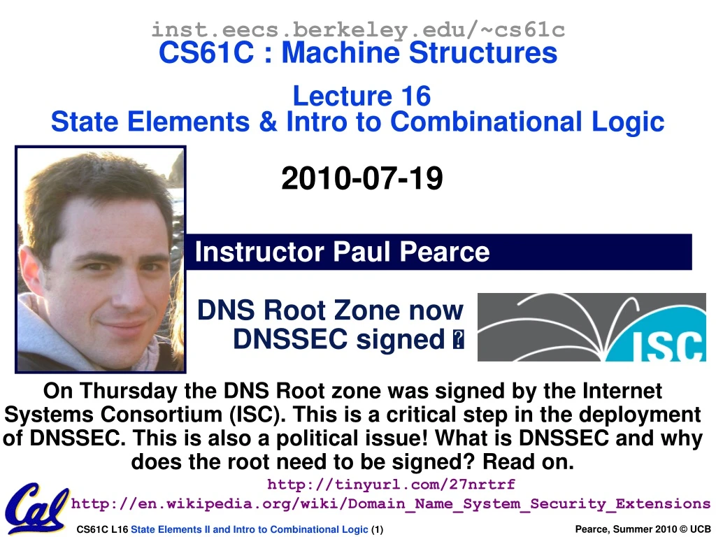
inst.eecs.berkeley.edu/~cs61cCS61C : Machine StructuresLecture 16State Elements & Intro to Combinational Logic2010-07-19 Instructor Paul Pearce DNS Root Zone now DNSSEC signed On Thursday the DNS Root zone was signed by the Internet Systems Consortium (ISC). This is a critical step in the deployment of DNSSEC. This is also a political issue! What is DNSSEC and why does the root need to be signed? Read on. http://tinyurl.com/27nrtrf http://en.wikipedia.org/wiki/Domain_Name_System_Security_Extensions
ISA is very important abstraction layer Contract between HW and SW Clocks control pulse of our circuits Voltages are analog, quantized to 0/1 Circuit delays are fact of life Two types of circuits: Stateless Combinational Logic (&,|,~) State circuits (e.g., registers) State elements are used to: Build memories Control the flow of information between other state elements and combinational logic D-flip-flops used to build registers Clocks tell us when D-flip-flops change Setup and Hold times important In review…
Maximum Clock Frequency • What is the maximum frequency of this circuit? Hint… Frequency = 1/Period Max Delay = Setup Time + CLK-to-Q Delay + CL Delay
Maximum Clock Frequency Max Delay How does the clock period relate to the Max Delay? Max Delay If the clock period is shorter than the maximum circuit delay, the circuit will not function correctly! Max Delay Here the clock period is longer than the max delay. This is wasteful, as the clock period can be shortened. Max Delay Now the clock period is minimized. Minimum period means maximum frequency!
Pipelining to improve performance (1/2) Extra Register are often added to help speed up the clock rate. Timing… Note: delay of 1 clock cycle from input to output. Clock period limited by propagation delay of adder/shifter.
Pipelining to improve performance (2/2) • Insertion of register allows higher clock frequency. • More outputs per second. Timing… Tradeoff: It now takes 2 clock cycles to produce a result!
Recap of Timing Terms • Clock (CLK) - steady square wave that synchronizes system • Setup Time - when the input must be stable before the rising edge of the CLK • Hold Time - when the input must be stable after the rising edge of the CLK • “CLK-to-Q” Delay - how long it takes the output to change, measured from the rising edge • Flip-flop - one bit of state that samples every rising edge of the CLK • Register - several bits of state that samples on rising edge of CLK or on LOAD
Finite State Machines (FSM) Introduction • You have seen FSMs in other classes. (Have you?) • Same basic idea. • We represent the functionality of a FSM with a “state transition diagram”. • With combinational logic and registers, any FSM can be implemented in hardware.
Finite State Machine Example: 3 ones… FSM to detect the occurrence of 3 consecutive 1’s in the input. Draw the FSM… Assume state transitions are controlled by the clock: on each clock cycle the machine checks the inputs and moves to a new state and produces a new output…
Hardware Implementation of FSM … Therefore a register is needed to hold the a representation of which state the machine is in. Use a unique bit pattern for each state. + ? = Combinational logic circuit is used to implement a function maps from present state and input to next state and output.
PS Input NS Output 00 0 00 0 00 1 01 0 01 0 00 0 01 1 10 0 10 0 00 0 10 1 00 1 Hardware for FSM: Combinational Logic In the reference slides we discuss the detailed implementation, but for now can look at its functional specification, truth table form. Truth table…
General Model for Synchronous Systems • Collection of CL blocks separated by registers. • Registers may be back-to-back and CL blocks may be back-to-back. • Feedback is optional. • Clock signal(s) connects only to clock input of registers.
Peer Instruction The period of a usable synchronous circuit is greater than the CLK-to-Q delay You can build a FSM to signal when an equal number of 0s and 1s has appeared in the input. AB A: FF B: FT C: TF D: TT
Peer Instruction Answer If not, will loose data! True! How many states would it have? Say it’s n. How does it know when n+1 bits have been seen? False! The period of a usable synchronous circuit is greater than the CLK-to-Q delay You can build a FSM to signal when an equal number of 0s and 1s has appeared in the input. AB A: FF B: FT C: TF D: TT
Administrivia • HW 6 due date has been moved to Wednesday at midnight • HW 7 moved back 1 day accordingly • HW 8 not moved! • Midterm being handed back after lecture. Stick around. • Discussion today will be covering common midterm problems. You should attend! • Grades and solutions will be online today. • Deadline for re-grades is next Monday. We will re-grade the entire test. This means grade could go down. • Goal is to have HW1-5, Proj 1, all graded by next Monday. • We’ll do our best to meet the goal.
Combinational Logic • FSMs had states and transitions • How to we get from one state to the next? • Answer: Combinational Logic
TT Example #2: 2-bit adder HowManyRows?
TT Example #3: 32-bit unsigned adder HowManyRows?
Symbol Definition A C B And vs. Or review – Dan’s mnemonic AND Gate AND
2-input gates extend to n-inputs • N-input XOR is the only one which isn’t so obvious • It’s simple: XOR is a 1 iff the # of 1s at its input is odd
Boolean Algebra • George Boole, 19th Century mathematician • Developed a mathematical system (algebra) involving logic • later known as “Boolean Algebra” • Primitive functions: AND, OR and NOT • The power of BA is there’s a one-to-one correspondence between circuits made up of AND, OR and NOT gates and equations in BA + means OR,• means AND, x means NOT
Boolean Algebra (e.g., for majority fun.) y = a • b + b • c + a • cy = ab + bc + ac (b • c) y= (a • b) + + (a • c)
BA: Circuit & Algebraic Simplification BA also great for circuit verificationCirc X = Circ Y?use BA to prove!
Canonical forms (1/2) Sum-of-products (ORs of ANDs)
Peer Instruction • (a+b)• (a+b) = b • You can use NOR(s) with clever wiring to simulate AND, OR, & NOT 12 A: FF B: FT C: TF D: TT
Peer Instruction Answer • (a+b)•(a+b) = aa+ab+ba+bb = 0+b(a+a)+b = b+b = b TRUE • You can use NOR(s) with clever wiring to simulate AND, OR, & NOT. • NOR(a,a)= a+a = aa = a • Using this NOT, can we make a NOR an OR? An And? • TRUE • (a+b)• (a+b) = b • You can use NOR(s) with clever wiring to simulate AND, OR, & NOT 12 A: FF B: FT C: TF D: TT
“And In conclusion…” • Max clock frequency is calculated based on max circuit delay • We pipeline long-delay CL for faster clock • Finite State Machines extremely useful • You’ll see them again 150,152, 164, 172… • Boolean algebra • Sum-of-products • Use this table and techniques we learned to transform from 1 to another
Midterm Stats! • (Recall, out of 190 pts) • Mean: 145.46 – 76.6% • Standard Deviation: 25.96 • Max: 181 • You seemed to have the most trouble on #2 and #3. • Mean was a bit lower than I’d like. • Remember, if class GPA at the end is below 2.7, I’ll bump everyone up!
Reference slides You ARE responsible for the material on these slides (they’re just taken from the reading anyway) ; we’ve moved them to the end and off-stage to give more breathing room to lecture!
Truth Table Gates (e.g., FSM circ.) or equivalently…
y = PS1 • PS0 • INPUT Boolean Algebra (e.g., for FSM) or equivalently…