Download
1 / 15
160 likes | 315 Views
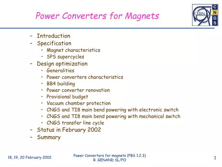
Power Converters for Magnets. Introduction Specification Magnet characteristics SPS supercycles Design optimization Generalities Power converters characteristics BB4 building Power converter renovation Provisional budget Vacuum chamber protection

E N D
Power Converters for Magnets • Introduction • Specification • Magnet characteristics • SPS supercycles • Design optimization • Generalities • Power converters characteristics • BB4 building • Power converter renovation • Provisional budget • Vacuum chamber protection • CNGS and TI8 main bend powering with electronic switch • CNGS and TI8 main bend powering with mechanical switch • CNGS transfer line cycle • Status in February 2002 • Summary
Specification (SPS supercycles) The second cycle is very restricting because we have to change the TI8 cycle to a CNGS cycle very quickly and it is foreseen to use the same power converter to feed both main bend chains (TI8 and CNGS) one after the other.
Design optimization (generalities) • The CNGS transfer line and the LHC transfer lines will be part of the SPS system. All the power converters will be controlled by the MUGEF. The MUGEF is the present SPS remote control system. • All the big converters will be pulsed for economical reasons (electrical power and thermal design). • A maximum of power converters will be recuperated from LEP and SPS. • The MBI magnets (TI8) and MBG magnets (CNGS) were specially designed to re-use the LEP main bend power converters. To reduce the CNGS project cost, it was decided to use the same power converter to feed MBI or MBG via a power switch (this solution saves about 1.5 million CHF). • All the power converters for TT41 will be installed in BB4 (existing building close to the shaft).
BB4 building The power converters will be installed in an existing building. It will need to be cleaned and the false floor will be adjusted to receive the power converters (this cost is in ST budget).
Power converter renovation The old power converters coming from SPS and LEP need refurbishing to improve their reliability • New electronics crate for regulation and remote control • New DCCTs (Direct Current Current Transformers) • New motor-driven circuit-breaker • Cabling modifications for new electronics adaptation and electro-magnetic compatibility improvement For the power parts of the power converters, the price of the refurbishment is about 30% of new converters.
Provisional budget 17 old converters + 2 spares + 18 MDGV/H (15 + 3 spares) + 1 New • New electronics + DCCTs 20x12= 240 • LEP converter modifications with new MCB 12x8= 96 • SPS converter renovation 7 units 242 • Power electronic switch for MBG 175x1= 175 • New COD for MDGV/H 18x2.5= 45 • New power converter 400A/125V 40x1= 40 • Spares 30 • Total 868 • Manpower (installation + commissioning) 40 • Total 908 • Remote control system (MUGEF, installation + commissioning) 100 • Total 1008 kCHF
Vacuum chamber protection • In case of power converter fault or power converter drift, there is a significant risk of irradiation and even perforation of the vacuum chamber. • We have to protect the vacuum chamber. To do that, the idea is to measure all the power converter currents in real time, to check if all are inside the tolerances on the flat top and to send a global extraction permit signal or an extraction abort signal to the kickers some milliseconds before extraction. • This new development must be done for the LHC transfer lines where the problem is more critical. CNGS will profit of this. • This work is in a process of realization by the remote control team in our group with the MUGEF system. • The first results in the laboratory are promising.
CNGS and TI8 main bend poweringwith electronic switch To comply with the SPS supercycle specification, we must use an electronic switch. Since it is not a safe element, if we want to give access in TI8 while CNGS is running, we will need mechanical switches to disconnect the MBI.
CNGS and TI8 main bend poweringwith mechanical switch only With more time between LHC cycle and CNGS cycle (~20s) and a number of operations limited (a few per day), it would be possible to use an easier and cheaper design. With only one mechanical switch, we can gain ~ 100 kCHF.
CNGS transfer line cycle • In a transfer line, the only significant performance portion is the flat top for the passage of the beam. But, to reduce electrical consumption and cooling power, we have to decrease the r.m.s. current value as much as possible. • The CNGS cycle is short. It is difficult to reduce the r.m.s. value because it involves high dI/dt. In addition, we need a flat top length of about 300 ms to reach the right values without overshoot. The initial estimate was 60% of the flat top value but with optimized current references, we can assure 55%.
Status in February 2002 • The power converters coming from SPS are already refurbished, delivered to CERN, cost committed or already paid. • The new power converters for the small correctors (MDGH/V) are delivered to CERN, cost committed or already paid. • The new power converter for the big corrector (MDS) is not yet ordered. • For the power converters coming from LEP and for MBI/MBG sharing system, nothing has been done yet. • For the remote control system, 80% of the cost is committed. • Budget situation:
Summary • Globally, for CNGS, the power converters and their control system can be looked upon as a copy of the LHC transfer line power converters. But: we have to study, design and manufacture the switch for MBI and MBG supply: - More difficult and expensive with electronic switch but runs with supercycle. - Easier and cheaper with mechanical switch only (gain ~ 100 kCHF) but waste of time during change of cycle (~ 20s) and number of operations limited (a few per day). If this solution is chosen, it will be possible to add the electronic switch in the future without problem (just money wise). • Presently some expenses have been delayed. If the situation is clarified in 2002, there will be no consequences on the planning (start up 2005), nor on the cost. If it is not the case, there will be consequences on both aspects.