Download

1 / 8
90 likes | 380 Views
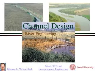
Channel Design. Channel Design. Channel design Channel alignment Shape Size Bottom slope Lined/unlined Cost issues (Lined channel may be more economical than an unlined channel). Channel Design. Case by case scenarios Design is done using trial and error

E N D
Channel Design • Channel design • Channel alignment • Shape • Size • Bottom slope • Lined/unlined • Cost issues (Lined channel may be more economical than an unlined channel)
Channel Design • Case by case scenarios • Design is done using trial and error • Verification of operational requirements is conducted after parameters selection • Alternatives and costs are examined (maintenance is added)
Channel Boundary • Non-Erodible Channel • Most lined channels and built-up channels can withstand erosion satisfactorily • Erodible Channel • Unlined • Flow velocity is kept low because of damage to bottom and sides • Minimum flow velocity in flows carrying a large amount of sediment should be such that the material being transported is not deposited in the channel
Rigid-Boundary Channels • Channel cross section and size are selected such that the required discharge is carried through the channel for the available head with suitable amount of freeboard • Freeboard is provided to allow for unaccounted factors in design, uncertainty in the selection of different parameters and disturbances of the water surface • , = freeboard in m, = coefficient varying from 0.8 (flow capacity of about 0.5 ) to 1.4 for a flow capacity exceeding 85
Rigid-Boundary Channels • Channel alignment is selected so that the channel length is as short as possible and at the same time meets other site restrictions (right of way, balancing cut and fill amounts) • Bottom slope is dictated by topography • Uniform flow assumptions (some cases gradually varied flow needed to assess the design suitability)
Rigid-Boundary Channel Design • Select value of roughness coefficient for the flow surface and select bottom slope based on topography and other consideration • Compute section factor from • Determine the channel dimensions and the flow depth for which is equal to the value determined in step above • Check that the minimum velocity is not less than that required to carry the sediment to prevent silting • Add a suitable amount of freeboard
Example • Design a trapezoidal channel to carry a discharge of 10 . The channel will be excavated through rock by blasting. The topography in the area is such that a bottom slope of 1 in 4000 will be suitable.