Download
1 / 12
120 likes | 280 Views
OPTICS OF MICE STEP V.0. Ulisse Bravar University of New Hampshire 26 June 2005. . -. STEP I: spring 2006. STEP II: summer 2006. STEP III: winter 2007. STEP IV: spring 2007. STEP V: fall 2007. STEP VI: 2008. MICE Steps. 2006. ……………. 2007. ……………. 2008.

E N D
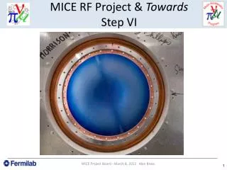
OPTICS OF MICE STEP V.0 Ulisse Bravar University of New Hampshire 26 June 2005
- STEP I: spring 2006 STEP II: summer 2006 STEP III: winter 2007 STEP IV: spring 2007 STEP V: fall 2007 STEP VI: 2008 MICE Steps 2006 …………… 2007 …………… 2008
MICE Step V.0 (1) STEP V STEP V.0 Should get 5-10 MV RF acceleration (limited by dark current) Shorter, less expensive, no coupling coil, (very limited optics flexibility) does this work in flip, RFoFo, non flip modes? These are mostly optics questions
MICE Step V.0 (2) • Spectrometers and AFC modules same as in all other MICE configurations. • NO coupling coil. • 2 RF cavities rather than 4. • RF dimensions do not change: length of one cavity = 43 cm. • Spacing between AFC modules reduced: LH to LH distance 2.75 m 1.35 m
Optics Goals (1) p = 200 MeV/c r (m) • Find optic solutions for all MICE steps and configurations. • i.e. choose currents for all 18 MICE coils to match the function as desired. (m) z (m) = 42 cm
Optics Goals (2) • Solutions for flip/non-flip/semi-flip operating modes: a) p = 140, 170, 200, 240 MeV/c; b) = 7, 15, 25, 42 cm in the middle of the LH2. • Assume B = 4 T in spectrometer for p = 200, 240 MeV/c. • Scale B with p for p < 200 MeV/c. Finding an optic solution means: • has the desired value and a minimum in the middle of the LH2 absorber; • has the desired value and d / dz = 0 in the two spectrometers; • B is constant within 1% in the two spectrometers; • J, BSURFACE and coil forces are within limits.
Optics of StepV.0 • Fix the distance between the two AFC modules. • Distance should be as small as possible, to reduce increase in the RF section. • Smallest distance = 1.35 m. • Once distance is fixed, absence of coupling coil implies there can be only ONE flip and ONE non-flip optic solution for StepV.0. • To improve performance, new optics software using routine CONMIN.F90 from NASA AMES.
Non-flip Mode (1) Bz field: • p = 200 MeV/c • min = 7 cm, 4 cm from center of LH • JFC = 125 A mm-2 (T) z (m)
Non-flip Mode (2) Beta function: • p = 200 MeV/c • min = 7 cm, 4 cm from center of LH • JFC = 125 A mm-2 (m) z (m)
Flip Mode (1) Bz field: • p = 200 MeV/c • min = 14 cm, 11 cm from center of LH • JFC = 194 A mm-2 (T) z (m)
Flip Mode (2) Beta function: • p = 200 MeV/c • min = 14 cm, 11 cm from center of LH • JFC = 194 A mm-2 (m) z (m)
Conclusions • Optic solutions for Step V.0 now available. • Work needed: A) do these solutions really work? i.e. determine cooling and scraping! B) are the currents, peak B-fields, RF E- fields and forces within tolerances?