Download
1 / 33
330 likes | 343 Views
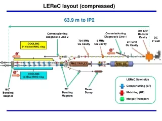
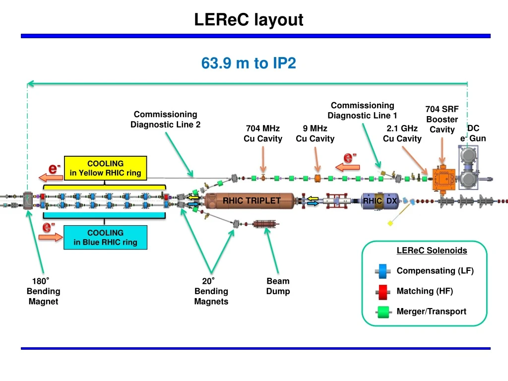
LEReC layout. 63.9 m to IP2. Commissioning Diagnostic Line 1. 704 SRF Booster Cavity. Commissioning Diagnostic Line 2. DC e - Gun. 2.1 GHz Cu Cavity. 704 MHz Cu Cavity. 9 MHz Cu Cavity. e -. e -. COOLING in Yellow RHIC ring. RHIC TRIPLET. RHIC DX. e -. COOLING

E N D
LEReClayout 63.9 m to IP2 Commissioning Diagnostic Line 1 704 SRF Booster Cavity Commissioning Diagnostic Line 2 DC e- Gun 2.1 GHz Cu Cavity 704 MHz Cu Cavity 9 MHz Cu Cavity e- e- COOLING in Yellow RHIC ring RHIC TRIPLET RHIC DX e- COOLING in Blue RHIC ring LEReC Solenoids Compensating (LF) Matching (HF) Merger/Transport 180° Bending Magnet Beam Dump 20° Bending Magnets
LEReC Meetings LEReC Beam Physics & Lattice LEReC Cathodes: usually Fridays at 9 pm, C.J. Liaw, JT LEReC DC Gun: Phone conference with Cornell usually Fridays, bi-weekly C.J. Liaw LEReC DC Gun to Booster Cavity: bi-weekly, S. Nayak LEReC Diagnostic Beam Line: weekly, K. Smith LEReC warm RF Cavities: Vendor phone conferences, Purchasing, tuner and window design, A. Zaltsman LEReC transport and cooling beam lines: bi-weekly, JT LEReC beam diagnostics: weekly, T. Miller
LEReCapertures 2.50 OD x 2.38 ID Valves 2.44 Commissioning Diagnostic Line 1 704 SRF Booster Cavity Commissioning Diagnostic Line 2 DC e- Gun 2.1 GHz Cu Cavity 704 MHz Cu Cavity 9 MHz Cu Cavity 5.0 OD x 4.78 ID RHIC TRIPLET RHIC DX 3.75 OD x 3.62 ID LEReC Solenoids Compensating (LF) Matching (HF) Merger/Transport Beam Dump 20° Bending Magnets 180° Bending Magnet
Cooling Section Installation Install stands Survey transport line location for magnetic measurements. Modify and install solenoids; Survey solenoids Install beam tubes – weld flanges - underway BPM’s assembled and leak checked BPM’s pre-surveyed Leak check and install bellows 3 - BPM Brackets
Cooling Section Installation Beamline shielded bellows BPM mounting shops parts and hardware. Standard Profile Monitor (2) and Emittance Slit (1) vacuum chambers. (1 ea) Std. Profile Monitor and Emittance Slit vacuum chambers held for testing. Special RF vacuum gaskets, nuts, and bolts BPM modified RF gaskets Repair and leak check 20o vacuum chambers Bake-out blanket or heater tape.
Installation Planing Install yellow side beam line 6 LF solenoids and 2 HF solenoids measured and accepted. 7 BPM chambers/supports, 1 emittance slit chamber 20o Y chamber, 2 – HF solenoid chambers, long 180otemporary chamber, bellows. Install blue side beam line 8 LF solenoids measured and accepted. 7 BPM chambers/supports, 1 - emittance slit, 1 – Profile Monitor 20o Y chamber, 180o temporary chamber, bellows
180o Dipole Magnet Neighborhood 2015 HIGH FIELD SOLENOID Standard RHIC Bellows Standard RHIC Bellows LOW FIELD SOLENOID Temporary Long Beam Tube ± 4.13” BPM YELLOW RHIC Beam Do not install LF solenoid, ES, and PM (shift vacuum chamber to right) BLUE RHIC Beam EMITTANCESLIT PROFILE MONITOR BPM Standard RHIC Bellows Temporary Beam Tube Yellow Side Need: Temporary long beam line chamber, special solenoid/ES support stand, (RHIC bellows) Blue Side Need: Temporary beam line chamber, special solenoid/ES support stand, (RHIC bellows) Remove Profile Monitor and Emittance SLIT Chambers kh
Installation Q3 Side Yellow Side End: emittance slit chamber, special solenoid chamber, 20o chamber, 20o stand, special solenoid/slit support stand Blue Side End: Standard profile monitor chamber, 20o chamber, 20o stand, special solenoid/PM support stand ID=4.78 ID=4.78 ID=4.78 Emittance Slit Chamber Profile Monitor Chamber
Cooling Section 2016 Installation Standard Profile Monitor Assemblies (3) (Hold 1 chamber for drive testing) 180o Magnet Assembly Magnet (magnetic measured) Hybrid PM/ES/BPMAssemblies (2) Vacuum chamber (measured) Magnetic field monitoring (characterized) Stand (non-moving) Bellows assemblies Emittance Slit Assemblies (3) (Hold 1 chamber for drive testing) Magnet shielding test assembly
12/15 Revised Transport Solenoid 1020 Steel (1.27 thick) Parameters: Conductor: #5 square, solid wire Total ampere turn: 2 x 7792.2 = 15,584.4 AT (plus some safety margin) Center field B = 647.3 Gauss Integral Bz^2 = 1.081E7 G2-cm (Req. 1.080E7 G2-cm) 16.40 15.13 14.80 Average J = 75 A/cm2 (1.78 thick) R (cm) 13.25 5.21 15.03 12.23
12/15 Revised Transport Solenoid • Need 13, will this number be changed? when • Diagnostic line solenoid – same spec’s? 840 Turns, #5 square copper conductor. 18.6 A, 7.2 V, 0.39 Ohms Will use for both Merger and Transport Solenoids Magnets designed for 2.5” pipe.
2.1 GHz Cavity Cavity fabrication contract awarded Windows ordered Frequency change and tuner section redesign complete ECN, revised drawings being checked Aluminum test cavity prepared Testing underway Tuner design Vacuum wave guide design
704 MHz Cavity Cavity fabrication requisition prepared Drawing revision for frequency change Requisition approved – RFP preparation Tuner design Window design
Gun to Booster – Meeting Tomorrow New Solenoid and Corrector Magnets Relocate BPM’s (button size/style??) Added bellows Added Profile Monitor
Gun to Booster Dipole Correctors moved offset (D/S) from solenoid center line. BPM moved offset (D/S) for solenoid center line. BPM configuration defined?? Quad and Skew Quad correctors (weak) shortened to allow BPM clearance.
Gun to Booster Define Laser box requirements Detail solenoid Defining correctors
LEReC Cooling Section Design Room LF & HF solenoid and 20o dipole magnets fabrication drawings(KH) Beam Diagnostics: BPM chamber and buttons (VDM) Beam Line 5” bellows with shields fabrication drawings (GW) 20o dipole vacuum chamber for impedence review (KH) 180o dipole fabrication drawings (KH) Spectrometer magnet (180o dipole) revisions (KH) 180o vacuum chamber + large sliding bellows fabrication drawing (KH) Beam Diagnostics ES W slit & chamber fabrication drawings (VDM) 20o dipole vacuum chamber fabrication drawings (KH) Cable tray and penetration drawings and excel sheet (AF) Beam Diagnostics: PM vacuum chamber fabrication drawings (GW) Beam Diagnostics: standard PM fabrication drawings (GW) Beam Diagnostics: special “hybrid” ES/PM/BPM fabrication drawings (GW) Beam line solenoid/BPM stands & vacuum chamber stand (VDM) 20o magnet stand drawing (KH) 180o magnet w/hybrid assembly BPM stand drawings (KH) on hold Magnetic shielding drawing and solenoid magnetic measurement test station (VDM) on hold In tunnel, magnetic measurement “mole” for stray field studies HF dipole, quadrupole, and skew quadrupole corrector drawings
LEReC Design Room Source Design Work DC Gun Vacuum Chamber Fabrication Drawings (JH) DC Gun SF6 Pressure chamber specification control drawings (JH) DC Gun cathode cooling design for Karl S. Cornell (JH) DC Gun stands (JH) DC Gun to SRF booster cavity beam line (JH) DC Gun to SRF booster cavity laser port, view port, profile monitor (JH) DC Gun to SRF booster cavity solenoid/corrector magnets (JH) DC Gun to SRF booster cavity BPM’s DC Gun cathode insertion drive assembly ERL Gun to Booster Cavity Modifications: U/S cathode to beam tube, FPC, D/S beamline & HOM (SS, JH) Cathode coating system cathode bakeout vacuum chamber & heater (KH & BM) Cathode coating system deposition vacuum chamber w/internal cathode transport system (KH) Cathode coating system transport vacuum chamber – ferris wheel (KH & WJ)
LEReC Design Room Other Work RHIC 1:00 move real estate drawings (V.DM.) Cryogenic system layout (RM) 2.1 GHz warm cavity spec. control drawings (MG) 2.1 GHz warm cavity tuner, wave guide, and warm test model (MG) 704 MHz warm cavity spec. control drawings (SP) Transport & Merger line layout (RM, KH) Locate booster cavity, solenoids, BPM’s, RF Cavities, PM’s, Diagnostic Lines Transport & Merger Line Solenoids (KH) Transport Line Solenoid Stands Transport & Merger Line Bellows and Pump Ports (GW) Transport & Merger Line CT’s (GW) Transport & Merger Line BPM’s (GW) Transport & Merger Line Correctors Transport & Merger Line Profile Monitors Merger Line Flying Wire Diagnostic Beam Lines and Components Kickers, RF cavity, beam dump,
180o Dipole Magnet Neighborhood 2016 BPM +YAG + Slit Assemblies HIGH FIELD SOLENOID PROFILE MONITOR LOW FIELD SOLENOID H/V Corrector ± 4.13” BPM YELLOW RHIC Beam PROFILE MONITOR EMITTANCE SLIT BLUE RHIC Beam BPM Quad/SQ Corrector kh
COOLING Section Solenoids CSY3 CSY2 CSY8 CSY4 CSY1 CSY7 CSY6 CSY5 YELLOW RHIC Beam BLUE RHIC Beam CSB1 CSB3 CSB2 CSB8 CSB7 CSB5 CSB6 CSB4 Emittance Slit 180° Dipole Low Field Solenoid High field solenoid Gate Valve High Field Solenoid Dipole Corrector Profile Monitor Hybrid BPM Gate Valve Quad Corrector 20° Dipole Bellows BPM Bellows BPM Profile Monitor Quad Corrector Low Field Solenoid Low Field Solenoid Emittance Slit kh
Diagnostics: Transport YAG BPM BPM BPM BPM BPM BPM BPM BPM 2.1 GHz Warm Cavity 704 MHz Warm Cavity 704 MHz Warm Cavity Solenoid(s) 11 locations Quadrapole(s) 2 locations Beam pipe size 2.38 ID does not match ERL Bake-out to near RHIC and near Booster Cavity?? ERL Buttons for BPM’s OK?? Profile Monitor drives from ERL, vacuum chamber? ERL emittance slit drive Commissioning line dipole angle 2nd 2.1 GHz cavity location? Another 20o dipole? e-Beam Transport BPM = 8 YAG = 1
Merger Beam Line To Commissioning Beam Line Flying Wire YAG From Electron Transport BPM BPM To Cooling Section Au Ion Beam Yellow Ring e-Beam Transport BPM = 2 YAG = 1 Flying Wire = 1 Beam pipe size 2.38 ID does not match ERL Bake-out to 200C?? near RHIC Flying wire system or equivalent TBD
Commissioning Beam Line Beam Sampling Technique for high power single macro bunch measurements YAG & Slit HVDC Deflector Solenoid From Transport Section To Merger Section Faraday Cup Medium Power Beam Dump (Full Power ~250μs) Fixed YAG Scanning YAG Profile Monitor Deflecting Cavity (704MHz) Separate Group Meeting Kicker TBS Merger solenoid?? Internal beam dump TBD Deflecting cavity design underway HVDC deflector TBD Another 20o dipole? TBD Fixed and Scan YAG’s dumps Commissioning B/L YAG = 3 Faraday Cup = 1 Defining Slit = 1
Merger/Transport Merger Solenoid BPM Corrector Gate Valve Quadrupole Bellows 20° dipole Need Quadrupole Magnet Spec’s Same as dump quadrupole? Move gate valve down stream of 20o? Instrumentation line Profile Monitor Wire Scanner Profile Monitor 9 MHz Cavity 704 Cavity Triplet Quadrupole Profile Monitor Gate Valve 20° dipole Beam Dump Quadrupole
IP 02:00 Profile Monitor Emittance Slit Merger Solenoid Profile Monitor 2.1 GHz Cavity 20° dipole Commissioning line
Diagnostics: Gun to Booster Cavity YAG Cathode Camera BPM BPM BPM BPM Faraday Cup Solenoid(s) YAG YAG BPM BPM DC Gun (Photocathode) DCCT Injection BPM = 6 YAG = 3 ICT = 1 DCCT = 1 Emittance Slit = 1 Halo Pairs = 2 Faraday Cup (& pick-ups) = 5 704 MHz SRF Booster Em-Slit ICT Vertical & Horizontal Halo Monitors & Pick-Ups Laser Injection Port 2.1 GHz Warm Cavity Cornell Layout GtB, Bake-out to 200C near DC Gun DC Gun instrumentation: • Large Button or ERL Buttons or Striplines?? • Profile Monitor in Laser Cross • Cathode Camera in Laser Cross
BPMs in Transport Section Small Dia. BPM Housings (2.38 ID), 10mm buttons ERL Buttons different size and shape