Download
1 / 39
430 likes | 678 Views
Operation of the S4700 FESEM. Quality SEM analysis is a matter of three factors 60% Sample- Preparation or type of sample 30% Knowledge of the operator 10% Type of instrument. Hitachi S4700. Instrument was installed in August of 1999 Has EDS, Backscatter, EBSD capabilities

E N D
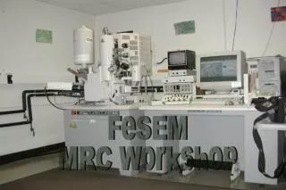
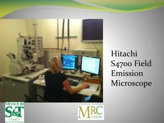
Operation of the S4700 FESEM Quality SEM analysis is a matter of three factors 60% Sample- Preparation or type of sample 30% Knowledge of the operator 10% Type of instrument
Hitachi S4700 • Instrument was installed in August of 1999 • Has EDS, Backscatter, EBSD capabilities • High resolution imaging, up to 500,000X • Low voltage imaging, down to 0.5kV
Basic Operation of the S4700 Each time you use the scope you need to fill the LN2 trap to the side of the scope.
Degasnot Degauss • If you are the first to use the scope then you must “Degas” the lower aperture • This is to clean the lower aperture. • Flip the switch located in the left of the instrument panel on the column down from “Heating” to “DEGAS”
Software Software You will be given a user account and you will set up a password that will be changed each time you use the scope. The initial logo should appear once you log in If it does not then open the SEM software from the FE-SEM icon on the desktop
This is the operating window of the 4700 software. All operation can be done with the mouse or with the help of the small control panel.
Log Book The microscope operating conditions will be written in a log book. These include the readings of the ion pumps, Ip1, Ip2, Ip3, the Vext, Ie, Vacc, date, user name, advisor and flash information if applicable
Set the HV using the HV control window and the drop down Vacc menu. HV’s between 0.5-30 kV are available
kV selection for a sample should be based on the type of analysis Samples that are non-conductors such as ceramics, glass, some oxides should be run at lower kV due to charging effects, which can cause problems with imaging. Samples that are conductors such as metals can be run at higher kVs but might not be necessary. Check the sample to see if the desired results are there at lower kVs. There is no need to blast the sample if the desired results can be obtained at a lower voltage. Remember the 2X rule for doing EDS on samples.
Insert Sample into Sample Exchange chamber • Once the sample has been correctly prepped, it should be screwed to the end of the insertion rod. • DO NOT BEND THE INSERTION ROD WHEN MOVING THE SAMPLE!
Chamber Scope • The S4700 is fitted with in infrared camera. This allows the user to see inside the sample chamber and avoid bumping into detectors when inserting samples and moving the stage • Chamber scope is turned on prior to inserting the sample into the sample chamber On switch
Sample Chamber • When the S.E.C. light on the front panel turns green open MV1 on the sample exchange door and allow the sample to be pulled into the sample chamber by the vacuum, watch on the chamber scope.
Column Setup • As the sample chamber pumps down, use the Column Setup for the type of SEM examination • The S4700 has 6operation modes for the column Ultra High Resolution Analysis Normal Long WD Magnetic UHRA
Working distance – True working distance and can be set. Condenser lens 1 - Default is 5, smaller numbers are bigger spot size, range is 1-16. DeGauss- To degauss the column Select Detector – Mixed for analysis and imaging Upper for high resolution Lower for analysis and samples that have slight charging
HV On • Turn on HV in the HV window when the sample chamber is at L X 10-3 • Check Ip3, if it is 1 X 10⁻⁵ thenDO NOT OPERATE • Note the Vacc, Ie and Vext and put in Log book
Imaging • Beam alignment • Select scan speed • Locate area of interest • Go to High Mag mode • Aperture alignment • Stigmate • Final Focus • Brightness and contrast • Capture image
Beam alignment • Focus the image • Click on “Beam alignment” in the “Alignment” window • Use the left knobs on control panel to adjust the beam in the middle of the target. • Will have to been done multiple times throughout operation.
Alignment window Beam align button Beam Move the beam to the center of the target Can be done in the grid window using the mouse
Select scan speed • 6 scan speeds • Fast 1 and 2 – Frame averaging Can be set in the “Signal Processing Window” • Slow 1-4 – are raster scan in seconds and are preset • 5 is a reduced area scan used to aid in focusing in a smaller area
Scan Speed buttons 1 2 1 2 3 4 5 Signal Processing window
Locate area of interest • Orient the sample using 5 axis stage X, Y, Z, Tilt, and rotation • Move the sample to locate an area of interest, with trackball, click and drag, stage arrows, change x, y, z, tilt, and rotate Trackball Mouse
Click and drag either the stage or the beam. This button for the beam. Blue hand cursor Stage arrows This button for the stage. Yellow hand cursor Stage Control Change x and y positions Rotate Z position Tilt
Go to High Mag mode • Use the Low Mag mode to locate an area of interest • Low Mag mode is 30-10,000x and can not be used for EDS • Use High Mag mode for EDS and imaging • High Mag mode is 250x to 500,000x • Not all samples can be imaged at 500,000x • Typical magnification is 25,000x to 250,000x
Aperture alignment • Check the beam alignment • Increase the mag, best done at the highest resolution • Click on the “Aperture Align” in the “Alignment” window • Use X and Y alignment knobs on control panel • Good alignment has little or no X or Y movement. Image should pulse or rotate
Low Mag/High Mag mode Aperture Alignment
Stigmate • Refocus the image after Aperture alignment • If the image skews out of focus it is out of sigmation. • Use knobs on the left of the control panel • Y Stigmate first, X Stigmate, fine focus then check Y and X stigmation again • Gross movement of the image indicates the sigmators need alignment • Use the Alignment window and proceed with sigmation alignment in the same manner as aperture alignment.
Final Focus • Select a slow scan speed to increase resolution • Refocus image
Brightness andcontrast • After focus do an “Auto Brightness and Contrast” • Brightness and Contrast can also be adjusted manually with the “Brightness and Contrast” monitor button
Auto Brightness and Contrast Button Brightness and Contrast Monitor Button
Capture Image • Select image capture options in the “Capture Image Window” • Capture an image with the “M” button on the main window. • Image will be temporarily saved to a “Capture Image Window” • “Capture Image Window” will appear, use the “Disk Icon” to save the image. • All Images are to be saved on the D drive • At completion images should be moved to the internet or recorded on a CD.
Capture Resolution-Change the size of the captured image Capture speed of the image- Frame averaging or slow scanning speed
Saved Capture Image Window Red “Saved”, image has been saved Red number in upper left corner is the active image Yellow number in the upper left corner is the next window to be occupied Disk Icon for saving the image
Blurred Images • Beam Alignement • Aperture Alignement • Stigmantion • Coarse Focus • Fine Focus • Building Vibrations • Stray Electric Fields • Tip Noise
Hints on Stigmation • Check Stigmation Alignment • Focus best possible image with fine focus with no “Skewing” • Y stigmate • X stigmate • Fine Focus
Tip Noise • Flash Tip • Open the HV Window • Select “Flash” • Click on Flash and watch the Ie number quickly appear in the window • Note this number in the Log Book • DO NOT operate if the Vext has changed 1.2 more than the most recent Flash Ie
Ie and Vext • Ie changes rapidly after flashing • “SET” a new Vext as the Ie drops • Best working conditions are at an Ie of >9 • If Ie goes up to 12 STOP operation and flash
The “On” button becomes a “SET” Button when HV is on Flashing button Ie can be changed, most common is 10 micro Amps