Download
1 / 30
370 likes | 1.01k Views
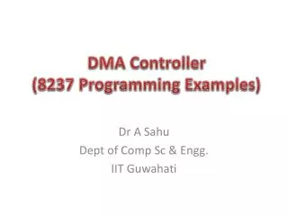
Interrupt Controller (Introduction to 8259). Dr A Sahu Dept of Comp Sc & Engg . IIT Guwahati. Hierarchy of I/O Control Devices. 2 Port (A,B), No Bidirectional HS mode (C) 4 mode timer. 8155 I/O + Timer. 8255 I/O. 2 Port (A,B) A is Bidirectional HS mode (C) Extra controls.

E N D
Interrupt Controller(Introduction to 8259) Dr A Sahu Dept of Comp Sc & Engg. IIT Guwahati
Hierarchy of I/O Control Devices 2 Port (A,B), No Bidirectional HS mode (C) 4 mode timer 8155 I/O + Timer 8255 I/O 2 Port (A,B) A is Bidirectional HS mode (C) Extra controls 8253/54 Timer 6 mode timer 8259 Interrupt controller 8237 DMA controller 8251 Serial I/O USART controller
How many I/O can be connected using 8255 • Two Port A & Port B • Port C as HS/INT port • Both can work Simultaneously Gr A Port A (8) I/O PA7-PA0 Group A Control Bi directional Data Bus D7-D0 I/O PC7-PC4 Gr A Port C (H 4) Data Bus Buffer Gr B Port C (L 4) I/O PC3-PC0 8 bit Internal Data Bus Read Write Control Logic RDb WRb A1 A0 RESET CSb Group B Control Gr B Port B (8) I/O PB7-PB0
How to connect multiple I/O Device • Use Interrupt as generalized mechanism to connect • Use priority resolver to connect them
Arbitration using a priority arbiter Micro-processor System bus 7 Inta 5 Priority arbiter Peripheral1 Peripheral2 Int 3 2 2 Ireq1 Iack1 6 Ireq2 Iack2 Peripheral1 needs servicing so asserts Ireq1. Peripheral2 also needs servicing so asserts Ireq2. Priority arbiter sees at least one Ireq input asserted, so asserts Int. Microprocessor stops executing its program and stores its state. Microprocessor asserts Inta. Priority arbiter asserts Iack1 to acknowledge Peripheral1. Peripheral1 puts its interrupt address vector on the system bus Microprocessor jumps to the address of ISR read from data bus, ISR executes and returns
Arbitration: Daisy-chain arbitration • Arbitration done by peripherals • Built into peripheral or external logic added • req input and ack output added to each peripheral • Peripherals connected to each other in daisy-chain manner • One peripheral connected to resource, all others connected “upstream” • Peripheral’s req flows “downstream” to resource, resource’s ack flows “upstream” to requesting peripheral • Closest peripheral has highest priority P System bus Peripheral1 Peripheral2 Inta Ack_in Ack_out Ack_in Ack_out Int 0 Req_out Req_in Req_out Req_in Daisy-chain aware peripherals
Arbitration: Daisy-chain arbitration • Pros/cons • Easy to add/remove peripheral - no system redesign needed • Does not support rotating priority • One broken peripheral can cause loss of access to other peripherals Micro-processor P System bus System bus Inta Priority arbiter Peripheral1 Peripheral2 Peripheral1 Peripheral2 Int Inta Ack_in Ack_out Ack_in Ack_out Ireq1 Int 0 Req_out Req_in Req_out Req_in Iack1 Ireq2 Daisy-chain aware peripherals Iack2
Micro- processor Cache Memory controller DMA controller Processor-local bus Peripheral Peripheral Peripheral Bridge Peripheral bus Multilevel bus architectures • Don’t want one bus for all communication • Peripherals would need high-speed, processor-specific bus interface • Too many peripherals slows down bus • Processor-local bus • High speed, wide, most frequent communication • Connects microprocessor, cache, memory controllers, etc. • Peripheral bus • Lower speed, narrower, less frequent communication • Typically industry standard bus (ISA, PCI) for portability • Bridge • Single-purpose processor converts communication between busses
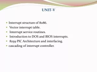
What is Interrupt • Interrupts alter a program’s flow of control • Behavior is similar to a procedure call • Some significant differences between the two • Interrupt causes transfer of control to an interrupt service routine (ISR) • ISR is also called a handler • When the ISR is completed, the original program resumes execution • Interrupts are used to interface I/Os • Interrupts provide an efficient way to handle unanticipated events
8259 Programmable Interrupt Controller (PIC) • It is a tool for managing the interrupt requests. • 8259 is a very flexible peripheral controller chip: • PIC can deal with up to 64 interrupt inputs • interrupts can be masked • various priority schemes can also programmed. • originally (in PC XT) it is available as a separate IC • Later the functionality of (two PICs) is in the motherboards chipset. • In some of the modern processors, the functionality of the PIC is built in.
8259: Programmable Interrupt Controller CPU 8259 Programmable Interrupt Controller IRQ0 INTR IRQ1 IRQ2 INTA IRQ3 IRQ4 IRQ5 IRQ6 IRQ7 8 bit Data Bus
Block Diagram of 8259 8259A Programmable Interrupt Controller IRQ0 8 bit Data Bus IRQ1 IRQ2 RDb WRb CSb A0 INT INTAb SPb/ENb IRQ3 IRQ4 IRQ5 IRQ6 IRQ7
Pin description • 8-bit bi-directional data bus, one address line is needed, PIC has two control registers to be programmed, you can think of them as two output ports or two memory location. • The direction of data flow is controlled by RD and WR. • CS is as usual connected to the output of the address decoder. • Interrupt requests are output on INT which is connected to the INTR of the processor. Int. acknowledgment is received by INTA. • IR0-IR7 allow 8 separate interrupt requests to be inputted to the PIC. • sp/en=1 for master , sp/en=0 for slave. • CAS0-3 inputs/outputs are used when more than one PIC to cascaded.
Block Diagram Architecture of 8259 INTAb INT Control Logic Interrupt Service Register Priority Resolver Interrupt Request Register IRQ0 IRQ1 IRQ2 IRQ3 IRQ4 IRQ5 IRQ6 IRQ7 Interrupt Mask Register Internal Bus
8259 Programmable Interrupt Controller • 8259 can service up to eight hardware devices • Interrupts are received on IRQ0 through IRQ7 • 8259 can be programmed to assign priorities in several ways • Fixed priority scheme is used in the PC • IRQ0 has the highest priority and IRQ7 lowest • 8259 has two registers • Interrupt Command Register (ICR) • Used to program 8259 • Interrupt Mask Register (IMR)
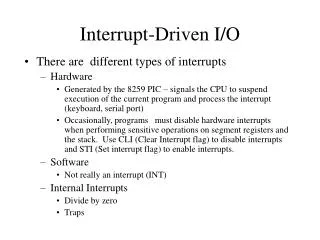
A Taxonomy of Pentium Interrupts Pentium Interrupts Processor Generated (Exceptions) Software Interrupts Hardware Interrupts Abort Faults Trap Maskable Non maskable
Exceptions • Exception Classification (processor-generated) • Fault • Return to the faulting instruction • Reported during the execution of the faulting instruction • Virtual memory faults • TLB miss, page fault, protection • Illegal operations • divide by zero, invalid opcode, misaligned access • Trap • Return to the next instruction (after the trapping instruction) • For a JMP instruction, the next instruction should point to the target of the JMP instruction • Reported immediately following the execution of the trapping instruction • Examples: breakpoint, debug, overflow
Exceptions • Abort • Suspend the process at an unpredictable location • Does not report the precise location of the instruction causing the exception • Does not allow restart of the program • Severe errors or malfunctions • Abort handlers are designed to collect diagnostic information about the processor’s state and then perform a graceful system shutdown • Examples: bit error (parity error), inconsistent or illegal values in system tables • Software-generated exception • INT n instruction generates an exception with an exception number (n) as an operand
Interrupt Processing in Real Mode • Uses an interrupt vector table that stores pointers to the associated interrupt handlers. • This table is located at base address zero. • Each entry in this table consists of a CS:IP pointer to the associated ISRs • Each entry or vector requires four bytes: • Two bytes for specifying CS • Two bytes for the offset • In PC: up to 256 interrupts are supported (0 to 255).
Interrupt Vector Table 03FF 03FE 03FD 03FC 0007 0006 0005 0004 0003 0002 0001 0000 IP High Byte CS Low Byte int type 255 Int type 0 Int type 1 IP High Byte IP Low byte IP High Byte CS Low Byte IP High Byte IP Low byte IP High Byte CS Low Byte IP High Byte IP Low byte Memory in Hex
Interrupt numbers range from 0 to 255 Interrupt number acts as an index into the interrupt vector table Since each vector takes 4 bytes, interrupt number is multiplied by 4 to get the corresponding ISR pointer Interrupt Number to Vector Translation
What Happens When An Interrupt Occurs? • Push flags register onto the stack • Clear interrupt enable and trap flags • This disables further interrupts • Enable interrupts • Push CS and IP registers onto the stack • Load CS with the 16-bit data at memory address • Load IP with the 16-bit data at memory address
Block Diagram Architecture of 8259 INTAb INT Control Logic Interrupt Service Register Priority Resolver Interrupt Request Register IRQ0 IRQ1 IRQ2 IRQ3 IRQ4 IRQ5 IRQ6 IRQ7 Interrupt Mask Register Internal Bus
Priority Modes • Fully Nested Modes • IR are arranged in IR0-IR7 and Any IR can be assigned Highest or lowest priority IR4=0 (high), IR3=7 (low) • Automatics Rotation Mode • A device after being served, receive the lowest priority with value 7 0123456712345670 23456701 • Specific Rotation Mode • User can select any IR for lowest priority • EOI: End of interrupt • Specific EOI Command • Automatic EOI: no command necessary • Non-Specific EOI: it reset the ISR bit
Masking and Prioritization • OCW (operation command word)
Reference • R S Gaonkar, “Microprocessor Architecture”, Chapter 15