Download

1 / 39
410 likes | 554 Views
Oklahoma DOT Perpetual Pavement Test Sections at the NCAT Test Track. Compression. Tension. Perpetual Pavement. Structure and materials are designed to provide a long service life (50 years +). 1.5” PFC. 3.0” SMA. 2.0” SMA. 3.0” 19 mm SP. 3.0” 19 mm SP. 8.0” 25 mm SP. 10.0” 25 mm SP.

E N D
Oklahoma DOT Perpetual Pavement Test Sections at the NCAT Test Track
Compression Tension
Perpetual Pavement Structure and materials are designed to provide a long service life (50 years +)
1.5” PFC 3.0” SMA 2.0” SMA 3.0” 19 mm SP 3.0” 19 mm SP 8.0” 25 mm SP 10.0” 25 mm SP 2.0” 12.5 mm 2% air voids 4.0” 19 mm 2% air voids 6.0” crushed stone Early Texas Perpetual Pavements Waco McAllen Cotulla 1.5” PFC 2.0” SMA 10.0”, 19 mm or 25 mm SP 3.0” 12.5 mm 2% air voids 8.0” lime-treated salvaged aggregate
Waco McAllen Cotulla 1.5” PFC 3.0” SMA 1.5” PFC 2.0” SMA 2.0” SMA 3.0” 19 mm SP 3.0” 19 mm SP 10.0”, 19 mm or 25 mm SP 8.0” 25 mm SP 10.0” 25 mm SP 3.0” 12.5 mm 2% air voids 2.0” 12.5 mm 2% air voids 4.0” 19 mm 2% air voids 8.0” lime-treated salvaged aggregate 16” Total HMA 6.0” crushed stone 20.5” Total HMA 16.5” Total HMA
Cost of 5 Miles of Pavement Assume 80’ width, $50 per ton How thick is too thick? Save 1” in over-design: $650,000 Save 2” in over-design: $1,300,000 Save 4” in over-design: $2,600,000
How thin is too thin? If the perpetual pavement structure is designed too thin, the risk of bottom-up cracking increases dramatically, defeating the purpose of the design and resulting in an expensive rebuild.
To design the appropriate pavement thickness, stresses and strains To design against potential bottom-up cracking, certain strain thresholds cannot be exceeded. } 1.5-3 in. PFC, SMA, etc. 3” to 6” High Shear Zone High Modulus Rut Resistant Material (Varies As Needed) Max Flexural Strain Pavement Foundation
Limiting Strain Theory • Based on laboratory beam fatigue data • “Small” strains will never induce cracking • Limiting strain at 75 to 125 microstrains • No bottom-up cracking below this level
These strains can be calculated based on total pavement thickness and material properties. However, the calculations would be based on assumptions made from previously collected data.
There are large deviations in the types of environment around the country, the types of materials used and the types of pavement specified. These deviations decrease the reliability of the assumptions made to calculate strains. Estimated Strain If the strains could be measured directly, using Oklahoma materials and mix designs, the data would be much more reliable.
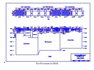
ODOT’S PERPETUAL PAVEMENT STRUCTURAL SECTIONS AT NCAT TEST TRACK PLAN VIEW SECTION N8 – 150’ SECTION N9 – 150’ 25’ TRANSITION 25’ TRANSITION 50’ TRANSITION
ODOT’S PERPETUAL PAVEMENT STRUCTURAL SECTIONS AT NCAT TEST TRACK PLAN VIEW SECTION N8 – 150’ SECTION N9 – 150’ 25’ TRANSITION 25’ TRANSITION 50’ TRANSITION PROFILE VIEW 2” SMA w/PG 76-28 3” SuperPave 19.0mm w/PG 76-28 3” SuperPave 19.0mm w/PG 64-22 2” RBL w/PG 64-22 3” SuperPave 19.0mm w/PG 64-22 3” RBL w/PG 64-22 *RBL = RICH BOTTOM LAYER
The maximum flexural strain is directly measured using a series of strain gauges installed at the bottom of the asphalt section. 1.5-3 in. PFC, SMA, etc. High Modulus Rut Resistant Material (Varies As Needed) Max Flexural Strain Pavement Foundation
If we have determined the strain for a 10” and 14” thick pavement, the thickness at the critical strain level can be interpolated / extrapolated ? MICROSTRAIN 10” 14” 16”
Accelerated Loading • Compress 10-15 years into 2 years • Heavy triples optimize safety and efficiency • Each axle loaded to federal legal bridge limit • Heavier loads induce unrealistic damage • No bridge spans to overload on NCAT track • Average gross vehicle weight 155k pounds
Long Term Response Measurements • Weekly - three passes of 5 trucks • Steer axle (12 kip), tandem (40 kip), 5 single axles (20 kip/axle) • 45 MPH • Measure strain • Measure pressure • Measure temps • Characterize long-term trends in strain response
To design the appropriate pavement thickness, stresses and strains The vertical compressive strain is directly measured using pressure plates installed at the top of the subgrade. 1.5-3 in. PFC, SMA, etc. High Modulus Rut Resistant Material (Varies As Needed) Max Flexural Strain Vertical Compressive Strain
Moisture sensors were also placed in the subgrade to continuously monitor soil conditions
Temperature probes were placed in the pavement to continuously monitor temperature at various depths
A datalogger is used to collect information from the different pavement sensors. In addition to the normal “slow speed” mode that continuously gathers data, a “high speed” mode can be used to collect 40,000 data points per second.
FWD TestingRut TestingSkid TestingInertial Profiler –Rutting Smoothness Surface Texture
Normal Operations • 55% of Strains below threshold
Supplemental FHWA Experiment N9 Instrumentation(Multi-Depth Array)
Strain vs. Speed and Temperature (ODOT and FHWA) • Primary Objectives • Study a perpetual pavement under a wider set of conditions • Primarily look at speed and temperature effects
Data Collected • 4 Speeds Tested • 15-45 mph (10 mph increments) • 4 Dates • April – May 2007 • Measured • Temperature • Tensile Strain
Investigations • Studied relationships • Speed-Strain • Temperature-strain • Combined • Strain Threshold • Load Durations • Relate to Frequency
Speed-Strain Strain at bottom of HMA Decrease with speed Temperature-Strain Strain at bottom of HMA Increase with temperature Relationships R2: 0.955-0.986
Strain Threshold • Tensile strain threshold: 100με
THANK YOU! QUESTIONS?